

DIY High Power LED Rechargeable Flashlight |

|

|
(#1)
|
|
RC-Monster Brushless
Offline
Posts: 2,085
Join Date: Sep 2007
|
DIY High Power LED Rechargeable Flashlight -
02.20.2010, 07:06 PM
OK, I just ordered a SSC P7 High Power LED and want to come up with a good Lithium Ion Power Source for it.
This 10 Watt LED is supposed to put out 900 lumens of bright white light. 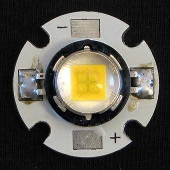 According to the specs, this LED operates on 3.0 volts to 4.2 volts. It draws 2.8 amps of current. So with that in mind, I needed a good Rechargeable Power Source. A Large 1S30P Battery Pack was constructed using 30 new cell phone batteries wired parallel. Each Battery is 800mah, so in theory, we have a 24,000mah Pack. Final size of the pack is very close to a 6 volt dry cell battery. 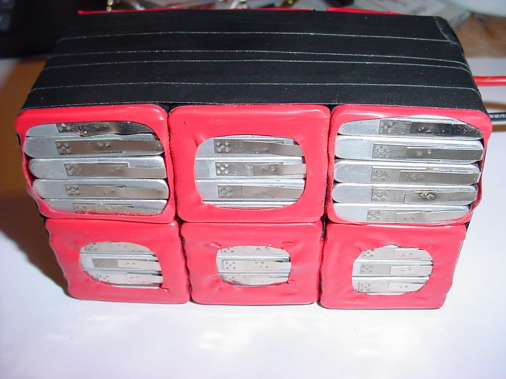 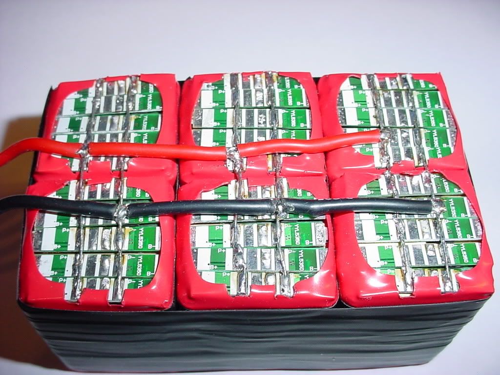 Each 800mah cell has it's own pcb to protect against overcharge/overdishcharge. Drawing 2.8 amps, this Pack should power the LED for 8.5 hours. Hmmm.............a few questions remain. Will this need a LED Driver and additional heat sinking to protect from thermal runaway? Thoughts? |
|
|

|
|
|
|
|
(#2)
|
|
RC-Monster Mod
Offline
Posts: 6,254
Join Date: May 2005
Location: Baton Rouge
|
02.20.2010, 07:40 PM
With what little research I've done on similar LEDs, a heatsink is a wise idea.
|
 |
|
|
|
|
|
(#3)
|
|
|
RC-Monster Brushless
Offline
Posts: 2,085
Join Date: Sep 2007
|
02.20.2010, 08:44 PM
Quote:
10 watts and its efficiency score equals 90 lumens per watt. These are also used in small tactical flashlights which run off a single 18650 lithium ion cell. These flashlights all all aluminum so the entire body is used as a heat sink. Runtime only being 1.5 hours tops. I'm thinking about using a 6 volt lantern style flashlight. Hmmmm...........perhaps an aluminum reflector assembly that is in thermal contact with the LED Star Mount? I still haven't found the answer to the question: Is an LED driver only required when using higher voltage? |
|
|
|
|

|
|
|
|
(#4)
|
|
RC-Monster Admin
Offline
Posts: 14,609
Join Date: Nov 2005
Location: Des Moines, IA
|
02.20.2010, 10:00 PM
All you need is a constant current source to keep the current at a certain value. The trouble might be finding a circuit that has a low enough drop out value so that most of the battery voltage is available at the output.
|
  |
|
|
|
|
|
(#5)
|
|
|
RC-Monster Brushless
Offline
Posts: 2,085
Join Date: Sep 2007
|
02.20.2010, 10:18 PM
Quote:
I'm wondering what happens? As the LED heats up, does it draw more current? The more current it draws, the hotter it gets, until thermal runaway blows it? I've been looking at this one: http://cgi.ebay.com/LED-Driver-Circu...item35a7073873 It regulates output to 2.8/3.0 amps. |
|
|
|
|
|
|
|
|
(#6)
|
|
RC-Monster Titanium
Offline
Posts: 1,152
Join Date: Sep 2008
|
02.21.2010, 09:56 AM
If you don't get enough feedback here you could try laserpointerforums. They should have some idea.
|
|
|
|
|
|
|
|
(#7)
|
|
KillaHurtz
Offline
Posts: 2,958
Join Date: Apr 2006
Location: Bucks Co, PA
|
02.21.2010, 01:09 PM
I have not played with the large leds, but whenever I built little led circuts, for rcs or flashlights, I simply used a resistor to limit battery current. Leds cause a voltage drop across them ( being diodes.) I simply calc'd the batt voltage minus the drop voltage (3-4v iirc for little white leds) then choose a resistor that would provide 20ma at that voltage. More stable the output voltage, more consistent the brightness. Best results were running off a ubec.
Idk so much about the big led. You have to calc the needed wattage of resistor as well. You may just need a small one to run that right off the batt, however I'd have to see more specs and sit down and work it out. For all the hassle Id prolly just buy the proper driver for such a large and pricely led. I also tested mine on a breadboard first to test my thinking and design. |
|
|
|
|
|
|
|
(#8)
|
|
RC-Monster Admin
Offline
Posts: 14,609
Join Date: Nov 2005
Location: Des Moines, IA
|
02.21.2010, 05:23 PM
Yes, an LED driver would be the best thing to use (especially the PWM type), but the battery supply at 1s is very close to the rating of the LED and I'm not sure if any driver or simple resistor would work well. The voltage drop of LEDs is effectively constant (actually, it's a function of drive current, but we will assume it's constant for the sake of argument). It's the current you really want to control here. The best and most reliable thing to do would be to use a test setup and measure the voltage drop of the LED at the current you want to drive it at. This will tell you the real value for this specific LED at the current you qant to drive it at, and you can properly design the circuit accordingly.
Using a resistor can be troublesome at these low voltages. Let's say for argument that he wants to use a resistor. The lipo nominal is 3.7v, and using the LED Vf and If values of 3.2v @ 2.8A, respectively. The resistor needed would be (v_supply-Vf)-If, or 0.18 ohms. But, at the peak battery voltage of 4.2v, the current would instead be 5.5A (too high), and the battery voltage of 3.2v at LVC might not even light the LED at all, or very dim. There just isn't enough voltage "headroom" to use a resistor effectively. And a constant-curent transistor setup also needs more voltage headroom as well. Using multiple LEDs in parallel can be done using a lower supply voltage, but the current is additive, and can get high, especially with the high power types. 20mA X 5 is only 100mA, but 5x2.8A in parallel is 14A.  This is why most reliable circuits use the series arrangement for multiple LEDs. I know you only have one LED here, but just thought I'd throw that in. This is why most reliable circuits use the series arrangement for multiple LEDs. I know you only have one LED here, but just thought I'd throw that in. The best way to power any LED (especially multiples) is to use them in series, use a supply voltage around 3-5v higher than the combined volteage drops, and use a constant current supply to create a consistent current no matter if the supply voltage fluctuates (as a battery will). Since the LEDs are in series, the total current draw will be the same 2.8A for all of them, you are just using higher voltage. Kinda the same idea as in BL where we use higher voltage for more efficiency. So, what does this all mean? Well, it means that making a proper driver for that single LED will be difficult using a 1s battery pack. It can be done, but the LED brightness will fluctuate as the battery voltage goes from fully charged to LVC. So, I would design your circuit with both max AND min battery voltage in mind to make sure you aren't exceeding the LED ratings while still providing some output. You're gonna find that a resistor (or driver) set for proper current at max battery voltage (4.2v) will result in a dimmer LEDs at anything lower. I created a page at my calc site to help with this stuff: http://scriptasylum.com/rc_speed/_led.html. It currently won't let you use 2.8A as an LED value and too low of a supply voltage for safety reasons since it was designed for normal LEDs, but you can still see what I'm talking about. There are some notes at the bottom which you will want to read, and don't forget to read the little help question marks. It pretty much goes over all the stuff I said above. You can use any voltage regulator IC as a constant current evice; it;s just a matter of configuration. But getting ones that are rated for over 1-1.5A are going to need to be ordered special. However, I've used the LM317T (1A 1.25v adjustable voltage reg) along with a pass transistor as a constant current device for up to 10A before. This regulator works the best as a constant current device because the min voltage headroom needed is just around 2.5v higher than the total LED Vf values. And as far as heat goes; you WILL need to heatsink the LED. 2.8A @ 3.2v is close to 9W. Failure to do so will result in a very short LED life! And, depending on what driver circuit you use, that may need to be heatsinked as well. |
|
|
|
|
|
|
|
(#9)
|
|
RC-Monster Brushless
Offline
Posts: 2,085
Join Date: Sep 2007
|
02.22.2010, 11:12 PM
The 900 lumen LED has arrived!
 A little testing here! This thing is like watching a camera flash, only it isn't a flash, it's constant! LOL Very White, Very Intense Light! I tested it for about 10 seconds at 3.7 volts. It was pulling 2.7amps and heated up to about 140 degrees. 140 degrees in 10 seconds. I believe some serious thought needs put into the heat sinking thing, but it does appear it's going to be worth it. We're talking spot light quality for 8.5 hours. The thing makes me see spots and I didn't even look directly at it. LOL |
|
|
|
|
|
|
|
(#10)
|
|
|
RC-Monster Mod
Offline
Posts: 6,254
Join Date: May 2005
Location: Baton Rouge
|
02.22.2010, 11:15 PM
Quote:

|
|
|
|
|
|
|
|
|
(#11)
|
|
TEAM FUSION
Offline
Posts: 2,041
Join Date: Jul 2006
Location: Iowa... Hawkeye country
|
02.22.2010, 11:33 PM
Maybe the thing to do here is configure the cells in a 3s pack for more voltage head room, and more convenient for charging also. Should require about 3 ohm resistor....
Funny this thread popped up... I was just working wiring up LEDs in my SC10 body over the weekend and talking to a local guy about doing his Baja truck today BG, I'm behind the times here... didn't know you had an Led calc... is there anything not on the script???? I heard you picked up a new project vehicle... gotta find the thread here. I know it's here somewhere lol Losi 8IGHT MM/Neu 1512 1900kv Kyosho 777 T4 MM 5700 B4 LRP XX4 MM 7700 old losi xxcr, MM4600 4s lipo 70mph+ |
|
|
|
|
|
|
|
(#12)
|
|
Soldermaster Extraordinaire
Offline
Posts: 4,529
Join Date: Apr 2007
Location: Plymouth, MA, USA
|
02.22.2010, 11:58 PM
|
|
|
|
|
|
|
|
(#13)
|
|
RC-Monster Admin
Offline
Posts: 14,609
Join Date: Nov 2005
Location: Des Moines, IA
|
02.23.2010, 12:05 AM
It would be simpler to use a LM317T vreg with a pass transistor, configured as a constant current source. The higher the voltage regulator rating, the more voltage headroom he is going to need.
You could also build a CC source using three diodes, a resistor, and a Darlington NPN transistor. This would require even less voltage headroom, but would also take a bit more design to do properly. |
|
|
|
|
|
|
|
(#14)
|
|
Soldermaster Extraordinaire
Offline
Posts: 4,529
Join Date: Apr 2007
Location: Plymouth, MA, USA
|
02.23.2010, 12:25 AM
Well the Fairchild FAN2500 looks promising with a 0.1v dropout. Plus they have a built-in switch on Vout. It's only rated for 100mA/300mA continuous/peak output so you would need about 35 of them... but who's counting?
 I suppose fewer of them could be used at the expense of higher dropout voltage. I suppose fewer of them could be used at the expense of higher dropout voltage.
|
|
|
|
|
|
|
|
(#15)
|
|
RC-Monster Brushless
Offline
Posts: 2,085
Join Date: Sep 2007
|
02.23.2010, 12:36 AM
I laid the LED on an 3" aluminum disk and ran it for about a minute straight. This kept the LED much cooler and only warmed the disk up lukewarm.
If the LED is only being fed it's rated voltage AND heat is controlled, why is a driver needed at all? I realize there are dimmer driver boards that allow modes of operation. 25%, 50%, 100%, flasher and even SOS signals. I just want 100% or nothing. Simple Enough. 
|
|
|
|
 |
«
Previous Thread
|
Next Thread
»
| Currently Active Users Viewing This Thread: 1 (0 members and 1 guests) | |
 Linear Mode

|
|

Powered by vBulletin® Version 3.8.11
Copyright ©2000 - 2026, vBulletin Solutions Inc.
vBulletin Skin developed by: vBStyles.com
Copyright ©2000 - 2026, vBulletin Solutions Inc.
vBulletin Skin developed by: vBStyles.com