

Milwaukee V28 lithium battery rewiring... |

|

|
(#1)
|
|
Check out my huge box!
Offline
Posts: 11,935
Join Date: Aug 2007
Location: Slidell, LA
|
Milwaukee V28 lithium battery rewiring... -
07.13.2009, 07:14 PM
Figured you guys would be interested in this...
So I have a v28 hammer drill, and had not used it in a while. Seemed like the battery would not take a charge correctly using the milwaukee charger, and the little "fuel gauge" was acting funny too. Pulled the pack apart and found that it has some sort of lvc/cell monitor as well as the fuel gauge, and it must have some sort of power interrupt as well. I measure the cell voltage before this apparatus and found the pack to be close to full,however measuring after the lvc it was about 5 volts lower without load. So i decided to can the internal lvc, and wire the pack straight to the output terminals. Now at the same time i decided that it would now be important to be able to balance charge the pack, using my hyperion 1210i and the 2 networked lba10 balancers. This posed an issue, as the lba balancers are designed to only handle 2 separate packs, up to 6s each, not 1 7 cell pack (the v28 has 7 emoli cells, std lipo voltage and 3000mah). So I tried a few things, including wiring a 3 and 4s balance harness to the pack, and making a series adapter for the 2 lba outputs. No dice. So i had to physically split the 7 cell pack into a 3s and a 4s, wire them independently and figure a method to run them in series for drill use and split them back in the 3 and 4s to charge. I ended up using some powerpole (first time using them and i really like them) connectors, cutting a square hole in the front of the case and gluing them in place. I made a small jumper to run the pos of the 4s pack to the neg of the 3s pack, and left the neg of the 4s pack and the pos of the 3s pack hooked to the main outputs that plug into the drill. I also ran wires off those main outputs to another set of powerpoles, so that I could plug directly into them to charge the cells. In the pic the small jumper (just 2 powerpole plus with a short wire to connect them) is plugged into the lower black and red powerpole plugs to bridge the wires necessary to run all 7 cells in series. I also had to make some plugs to allow the balancer wires to exit, as I did not want pigtails hanging out of the pack. Used some 6 pin mpx? plugs i bought a while back from hobby city. One has 4 of the pins used for the 3s balance tap, and the other has 5 pins used for the 4s. So after a bunch of soldering I got it all back together and gave it a try, works like a charm! Pictures will be alot clearer than the explanation... And yes, there is a bunch of wire inside that poor casing. I could not be bothered to make all of the wires perfect length, so they are all the same length, all 9 of the balancer wires, and 6 14 gauge wires are in there as well. 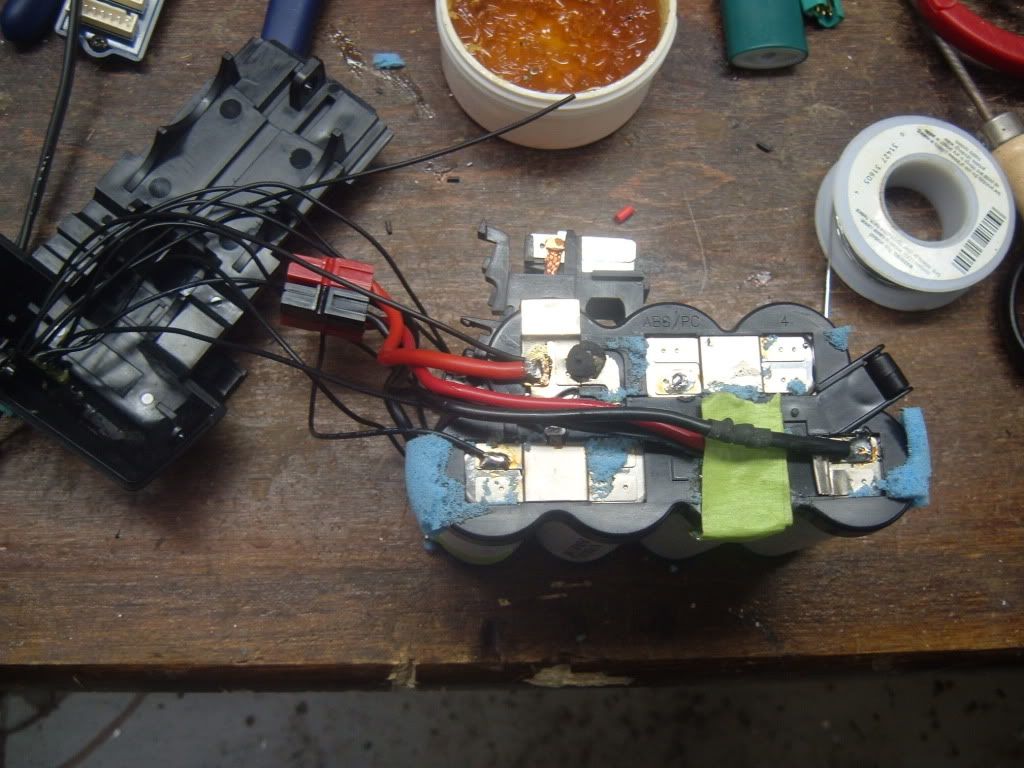 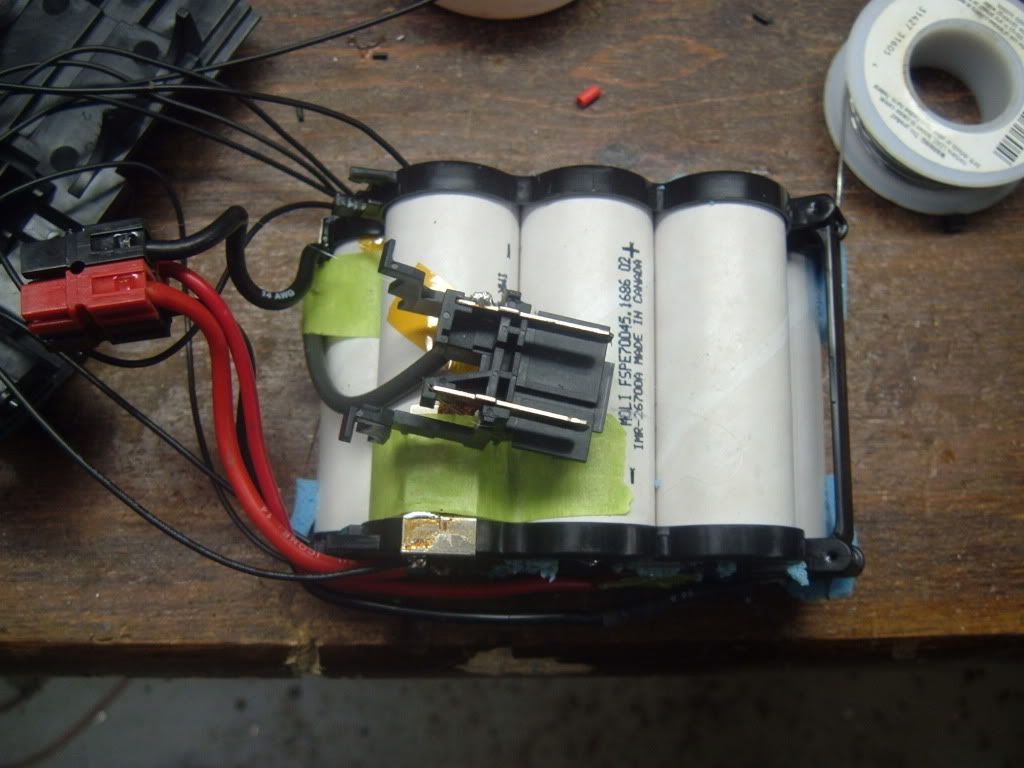 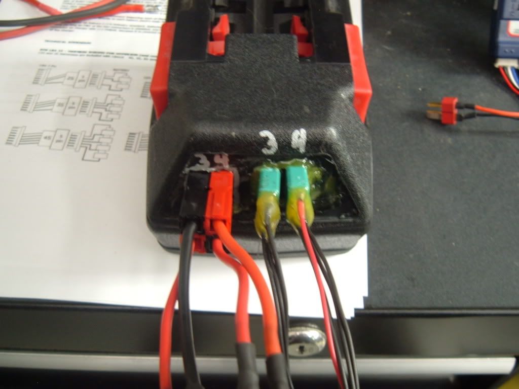 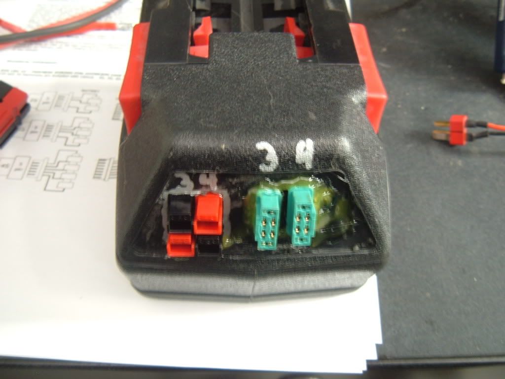 
|
|
|

|
|
|
|
|
(#2)
|
|
Destroyer of Tires
Offline
Posts: 626
Join Date: Feb 2009
|
07.13.2009, 10:06 PM
The thread title should've been "the worlds most complicated battery to charge". But thats some interesting info, for anyone considering using any of these packs for anything.
Powerpoles are good connectors, I like them better than deans. But expect whatever you put them on to have those connectors forever. They don't come apart easy, unless you use a cutoff wheel to cut them open. I switched a friend over from them once and some stuff had short leads that I couldn't cut any shorter, what a pain that was getting them apart. |
|
|
|
|
|
|
|
(#3)
|
|
Check out my huge box!
Offline
Posts: 11,935
Join Date: Aug 2007
Location: Slidell, LA
|
07.14.2009, 12:05 AM
They come apart very easily. Just take a dental pick and lift the contact up so it clears the flat spring. Then pull on the wire and the contact will slide out. I soldered these (45 amp models) and they are much easier to assemble and solder than deans, plus I did not have to desolder them to put the shrink on, forget that at least once every 5 or so deans plugs I solder). I may try a set out on my muggy and see if they can handle the current, if so I may have alot of deans for sale!
For what I did here I doubt any other connector would allow me to make a bridge and still be able to use another harness for charging. I will post a pic of the batter with the bridge in, makes more sense than the description. I will also post a how to with pics on how to take them apart... The instructions on anderson's site are not that great. I was going to buy the crimper but see no need, I just cut the "wings" down a bit with dikes and tin the bottom of the "trough" and then solder the pre-tinned wire in. Nice and neat, no heat shrink and no burnt plastic if you slip with the iron. Good stuff. |
|
|
|
|
|
|
|
(#4)
|
|
Check out my huge box!
Offline
Posts: 11,935
Join Date: Aug 2007
Location: Slidell, LA
|
07.14.2009, 12:07 AM
And this was a bit complicated. If only I had a 720i, or the pack was 6s... Or a123 so balancing was not so important. I may try to scare up some crapped out packs and put a123 cells in there... They are the same size as the emoil cells. Little less voltage and runtime, but I doubt the drill would mind. Or just put some 3200 30c lipo cells in a modded case... More power and runtime.
|
|
|
|
 |
«
Previous Thread
|
Next Thread
»
| Currently Active Users Viewing This Thread: 1 (0 members and 1 guests) | |
 Linear Mode

|
|

Powered by vBulletin® Version 3.8.11
Copyright ©2000 - 2026, vBulletin Solutions Inc.
vBulletin Skin developed by: vBStyles.com
Copyright ©2000 - 2026, vBulletin Solutions Inc.
vBulletin Skin developed by: vBStyles.com