

|
|
Quark ESC Power Board Comparisons/Mods |

|

|
(#1)
|
|
RC-Monster Brushless
Offline
Posts: 2,085
Join Date: Sep 2007
|
I am in the infant stages of challenging myself to build a custom power board that will use higher amp MOSFET's but be controlled by the Quark Brain Board and Software.
The MOSFET's that I plan on using are: 75545P N236 A1 The absolute max ratings are 75A, 80V, 0.010 Ohm, N-Channel, UltraFET Power MOSFET. This style has compatible on/off speeds with the FET's used in the Quarks. I noticed in looking up information on the 75545P that since it's a N-channel MOSFET, it is neither a PNP nor a NPN FET. It doesn't have a preference to which polarity of DC current controls it's gate. I've been digging around in my 33Amp ESC doing some research on it's FET's. This ESC uses two types of FET's. The TPC8107, Silicon P-Channel MOS Type(PNP type), and the IORP550C NPN Style FET. These have max voltage limitations of 30 volts. The data sheets don't show a max amp rating, but it can't be much. I was wondering how to adapt the circuits to the N-channel MOSFET's knowing it was going to be a big problem until I began looking at my Quark 80 amp ESC. The Quark 80 Amp uses 24 of the the 22N03S MOSFETs! These are N-Channel also. The Data sheet on this MOSFET shows absolute ratings of a 30 volt limitation with a 50 amp current limitation. Much Better! I can only see the front 12 MOSFET's, and I'm not tearing my Quark 80 completely down just to see. Does anyone know if the MOSFET's on both sides of the board are the same? I'm wondering also, What are the numbers on the ones used in the Quark 125 amp model? I looked around at some of the other posts pics, and I can't make it out. They appear to be the same, plus the 125 amp model uses 36 of them. I would also like some FET input on the Quark 65 amp model if anyone has access to that. I know that adapting a larger MOSFET in place of a smaller MOSFET will be much easier to do than using a brain board that currently controls a NPN, PNP Fet arrangement. I'm going to look at this in two steps. Goal #1. Use a MOSFET controller like the 80 amp or 125 amp to control a custom built powerboard capable of 200 or 300 amps continuous. Same software, same voltage limitations. Goal #2. Is it possible to regulate the voltage to the existing logic controller in such a way, that it will control a power board that is at a much higher voltage? Regulate incoming power to the logic board, and also incoming feedback from the motor? I'm a long way from answering this one, but there must be a way. Any help, or input would be greatly appreciated. |
|
|

|
|
|
|
|
(#2)
|
|
RC-Monster Admin
Offline
Posts: 14,609
Join Date: Nov 2005
Location: Des Moines, IA
|
11.02.2007, 09:30 PM
Wow! First of all, let me say you are tackling a complex project here!
When you say PNP/NPN, I assume you are familiar with bipolar transistors. Transistors are "current" driven, have a current gain (beta), and have a set collector to emitter voltage drop even at saturation. MOSFETs are voltage driven (they don't load down driving circuits) and their drain to source v drop is determined by the Rdson value and current flow. Think of them more like a faucet where the source is the water tank, the drain is the output, and the gate is the valve. Rough analogy, but sufficient. There are other differences, but you see what I mean - it's like comparing apples to oranges. Aside from being N or P channel, are they enhancement or depletion types? I would think you would NEED enhancement types, but I dunno. Sorry I can't help you any further on this as I've never really dealt too much with FETs at the design level. The Quark 125 uses the same FET parts, just more of them. IIRC, they are the same on both sides. |
  |
|
|
|
|
|
(#3)
|
|
|
RC-Monster Brushless
Offline
Posts: 2,085
Join Date: Sep 2007
|
Quote:
I like your analogy. It's a good one since DC Current only flows one way. I've often thought like that too. I find myself switching back and forth between the two sets of data sheets comparing figures and I find no reference on either as being enhancement or depletion types. I think I'm in the ball park on compatibility. The donor drive unit that gave up these bigger MOSFET's served as a controller for a 36 volt drive motor. The motor is brushless and is a 6.6kw unit. This was not a sensorless setup by any means. It pushed around a 9500 pound Industrial truck at 9mph. The Controller these came out of has an extensive brain board that uses an encoder bearing in the motor to calculate timing. Based on encoder information, the controller knows motor speed and armature postion. Much like the Novak sensor based setups. I want a high Amperage Car Controller that will do multipole motors! A HV setup that will do 36 volt reliably would be a dream come true. 
|
|
|
|
|

|
|
|
|
(#4)
|
|
RC-Monster Aluminum
Offline
Posts: 748
Join Date: Oct 2005
|
11.02.2007, 10:15 PM
I'm sorry but I do not think that this is a good idea, based on your questions...
P.S. But if you willing to try, then shoot me PM and I will try to help you out with design. |
|
|
|
|
|
|
|
(#5)
|
|
|
RC-Monster Brushless
Offline
Posts: 2,085
Join Date: Sep 2007
|
Quote:
Thanks for volunteering to lend a hand. I appreciate that. I have followed some of your work and respect you as being one of the most knowledgeable people around here on this. I look at myself in this, like a student, that has alot to learn. But I like to challenge myself, sometimes things work out for the better, and sometimes they don't. But in the process, along the way, knowledge is gained. I have spent several hours tonight just reading about principles of operation. There's alot to learn, but this is how we grow. 
|
|
|
|
|
|
|
|
|
(#6)
|
|
|
RC-Monster Aluminum
Offline
Posts: 748
Join Date: Oct 2005
|
11.02.2007, 11:20 PM
Quote:
Creating threads on modifying ESC's my goal was to help hobbyists to improve their controllers without knowing too deep how it works. And for any good electrical engineer all my tricks are quite obvious, but to design good ESC will require more then just EE...experience helps allot! :) |
|
|
|
|
|
|
|
|
(#7)
|
|
RC-Monster Brushless
Offline
Posts: 2,085
Join Date: Sep 2007
|
11.02.2007, 11:39 PM
Ok, according to the data sheets, here's the resistence values:
Big MOSFETS - RDS(ON)= 0.010 ohms max with 0.0082 ohms typical No Gate Resistence value listed Quark 80 amp MOSFETS - RDS(ON)= 2.2 megaohms Gate Resistence = .6 ohms The Big Mosfet data sheet doesn't list a Gate resistence value. I wonder how much current the Gate lead circuit in the Quark 80 Brain board can support? |
|
|
|
|
|
|
|
(#8)
|
|
|
RC-Monster Aluminum
Offline
Posts: 748
Join Date: Oct 2005
|
11.02.2007, 11:57 PM
Quote:
This parameter responsible for FET's frequency response, noise and etc when you run simulation and important in design stage. "Big" fets are usually slow, bulky and rated for high power plus in most cases have lower RDS(On) then "smaller" ones. You need to check for fet driver part number in Quark 80 brain and study the circuit around it. To calculate required Voltage and Current check for switching frequency and total gate charge. Then do the same calc with different loads and temps. |
|
|
|
|
|
|
|
|
(#9)
|
|
RC-Monster Admin
Offline
Posts: 14,609
Join Date: Nov 2005
Location: Des Moines, IA
|
11.04.2007, 03:34 PM
If you like that, you should check out a TV flyback transformer sometime! Don't know if it would produce enough current to kill, but the voltage sure hurt!
|
|
|
|
|
|
|
|
(#10)
|
|
|
RC-Monster Dual Brushless
Offline
Posts: 5,139
Join Date: Sep 2006
|
11.04.2007, 04:20 PM
Quote:
|
|
|
|
|
|
|
|
|
(#11)
|
|
|
Z-Pinch racer
Offline
Posts: 3,141
Join Date: Nov 2006
Location: SK, Canada
|
12.15.2007, 07:14 PM
Quote:
 Come stop by and I will show you my 'Tesla Coil' running at ~700,000volts AC... very load, and looks VERY deadly, however you can hold you hand in the arcs and you only feel very minor shocks... that's because it's running at very high frequencies ~500khz resonant freq. I have heard of ppl using those flyback transformers in small Tesla Coils for the primary circuit. |
|
|
|
|
|
|
|
|
(#12)
|
|
RC-Monster Admin
Offline
Posts: 14,609
Join Date: Nov 2005
Location: Des Moines, IA
|
11.04.2007, 05:50 PM
Yeah, that's 12,000v. Usually, since the voltage is stepped up, the current is stepped down so there isn't much current available. But, it only takes ~15mA to kill (that's 0.015A)...
|
|
|
|
|
|
|
|
(#13)
|
|
RC-Monster Dual Brushless
Offline
Posts: 5,139
Join Date: Sep 2006
|
11.04.2007, 06:00 PM
Good thing for fuses and circuit breakers LOL.
|
|
|
|
|
|
|
|
(#14)
|
|
RC-Monster Brushless
Offline
Posts: 2,085
Join Date: Sep 2007
|
11.04.2007, 06:13 PM
I decided to take a few pictures of this HV power board before I completely tear down the original configuration and perhaps learn a few things from analyzing what they've done.
I notice that they have all the gate leads tied together through a series on resistors inline. I'm not sure what effect this will have, but I think it governs the amperage the gate leads are allowed to draw. The Blue Component marked "Wima" is like a small Capacitor, it will charge up under an Ohm meter. This is connected between the source and the drain. A Cushion? I would think they need to charge up first, before full output power is seen. 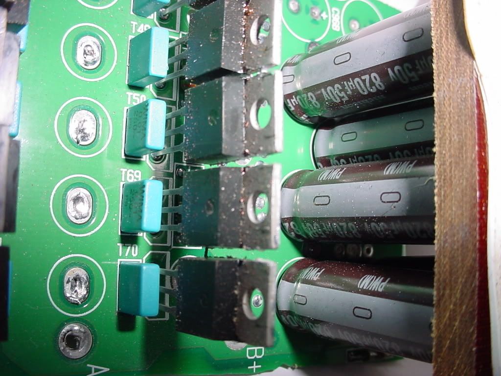 Wait second! Are those more Low ESR Capacitors I see? (*Joke*) 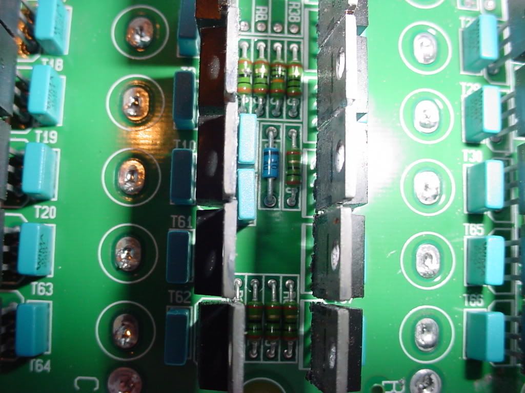 I'm thinking about using this board for testing. Strip the resistors, and use the existing pathways for the Mosfets. The Caps are already in place too. This thing is huge though. It's 8" x 3" x 2". If I can make it work and put it through some testing, I'll reconfigure the entire thing to make it compact. Absolute ratings for this board is 375 amps. Perhaps it will do 300 amps continous with the proper heat sinking. (which I have also) Come to think of it, How am I going to test this thing? I know a Data Logger is in order, but to seriously load it? Hmmmmm...........aah well, one thing at a time. I have a AXI 4130/20 that I could bolt a 20" inch prop onto. It's rated for 8 Lipo cells. Maybe open up the doors and blow the house out. LOL |
|
|
|
|
|
|
|
(#15)
|
|
Brushless Heavy Weight....
Offline
Posts: 1,954
Join Date: Sep 2005
Location: Kingsville, Ontario
|
12.15.2007, 02:27 PM
When you guys have the ESCs ready.. I'll be sh*ttin' my pants to test it out.. I've gotta make use of all my lipos...
http://www.geocities.com/aqwut 1HP (electric) = 746 Watts. Everything is brushless!! |
|
|
|
 |
«
Previous Thread
|
Next Thread
»
| Currently Active Users Viewing This Thread: 1 (0 members and 1 guests) | |

 Hybrid Mode
|
|

Powered by vBulletin® Version 3.8.11
Copyright ©2000 - 2026, vBulletin Solutions Inc.
vBulletin Skin developed by: vBStyles.com
Copyright ©2000 - 2026, vBulletin Solutions Inc.
vBulletin Skin developed by: vBStyles.com