

Combine balance taps for 2x 2S2P as one 4S |

|

|
(#1)
|
|
RC-Monster Carbon Fiber
Offline
Posts: 200
Join Date: Jan 2007
|
Combine balance taps for 2x 2S2P as one 4S -
05.07.2007, 09:26 AM
I need some electronics help...
Can I somehow wire the balance taps of two Maxamps 2S2P (with Apache/Hyperion connectors) packs to act as one 4S pack ? I probably should like to a pin-layout of the Apace/Hyperion connector but I have only found a few in PDF's available on the net. Also see post 24-25 in http://www.rc-monster.com/forum/show...&highlight=dpm I cant figure out what "You just daisy chain the LVC connectors" means. |
|
|

|
|
|
|
|
(#2)
|
|
RC-Monster Admin
Offline
Posts: 14,609
Join Date: Nov 2005
Location: Des Moines, IA
|
05.07.2007, 10:47 AM
It's kinda hard to explain in words, but take a look at the bottom of this page. That should help you visualize what is meant by daisy-chaining.
If you are hesitant, I would see if you can get a cable pre-made to do what you want. If done incorrectly, you could literally burn up a balancer wire if hooked up wrong, but it depends on how you have it set up. |
  |
|
|
|
|
|
(#3)
|
|
RC-Monster Carbon Fiber
Offline
Posts: 200
Join Date: Jan 2007
|
05.07.2007, 11:01 AM
Just a check to see if I got it right, If I want to use a 4S capable LVC to monitor both packs of my HV-Maxx truck I should use the "Hyperion connector 2S + 2S, balance connector only"
Am I right ? If I make a connection harness what volts should I expect to see at the pins on the connector towards my LVC ? (I guess a voltage check would be good to to before I hook it up and fry my LVC...) |
|
|
|
|
|
|
|
(#4)
|
|
RC-Monster Admin
Offline
Posts: 14,609
Join Date: Nov 2005
Location: Des Moines, IA
|
05.07.2007, 11:08 AM
Well, on the end of the "combiner", you'd see each of the cell voltages. And from the leftmost pin to the rightmost pin, you'd see the full pack voltage.
Question: Does this LVC you plan to use monitor each cell individually? If it just monitors the full pack voltage, you can simply tap off the main power wires, just like you'd do to install a UBEC. |
|
|
|
|
|
|
|
(#5)
|
|
RC-Monster Carbon Fiber
Offline
Posts: 200
Join Date: Jan 2007
|
05.07.2007, 11:11 AM
Its the CellPro from FMA direct http://www.fmadirect.com/detail.htm?...117§ion=45
My understanding is that it should be capable of monitoring each cell but if you have the time, please verify it.... |
|
|
|
|
|
|
|
(#6)
|
|
RC-Monster Admin
Offline
Posts: 14,609
Join Date: Nov 2005
Location: Des Moines, IA
|
05.07.2007, 11:23 AM
Yeah, it looks like it does monitor each cell. So, you'll need to make a balancer harness Y adaptor.
There is very little difference between my two diagrams for "2s + 2s, using main leads" and "2s + 2s, balance connector only". |
|
|
|
|
|
|
|
(#7)
|
|
|
RC-Monster Carbon Fiber
Offline
Posts: 200
Join Date: Jan 2007
|
05.07.2007, 11:39 AM
Quote:
|
|
|
|
|
|
|
|
|
(#8)
|
|
RC-Monster Admin
Offline
Posts: 10,480
Join Date: Feb 2005
|
05.07.2007, 11:46 AM
if you put them in series, it goes like this;
one red and black wire are unused and are considered a connection to make a 4S pack, a 2S pack uses 3 wires. one 0V/black, one 3.7 and one 7.4. between the 3.7 and 7.4 tab is a 3.7V again; now if you put them in series for 4S, you need a total of 5 wires. and each wire differs the 3.7V of the cell. the two most outer wires measure ~18.5V. |
|
|
|
|
|
|
|
(#9)
|
|
RC-Monster Carbon Fiber
Offline
Posts: 200
Join Date: Jan 2007
|
05.07.2007, 01:15 PM
I cant relly understand what Y connection option I should use with the Hv-Maxx (2x pack serial connection made internally in ESC).
Remeber that I wont use it for balancing the packs but for a LVC that will monitor all cells in both packs and shutdown if any cell goes low. Should I use:  Or: 
|
|
|
|
|
|
|
|
(#10)
|
|
RC-Monster Admin
Offline
Posts: 10,480
Join Date: Feb 2005
|
05.07.2007, 01:19 PM
You need to use picture 2 for your cell shield.
|
|
|
|
|
|
|
|
(#11)
|
|
RC-Monster Carbon Fiber
Offline
Posts: 200
Join Date: Jan 2007
|
05.07.2007, 03:10 PM
Serum and BrianG, thanks for your help.
I will use the CellPro DSM LVC but I guess the connections will be the same. Also this is what I got from FLMdirect support: "Here is how to wire it. You will need our 2mm pigtail. Pin 1 is black and should connect to your speed control black. Pin 2 should connect to 4V Node 1. Pin 3 should connect to Red of the lower pack. (Center tap in the speed control) Pin 4 should connect to 12V Node 1 on the upper pack. Pin 5 is red and should connect to the red of the speed control (16V) You can easily verify that you wired correctly before connected the DPM. On the 2mm Cell Pro pigtail, you should verify the following voltages. Put the Negative probe of your meter to speed control ground. Pin 1 (Black) is 0V Pin 2 (White) is 4V Pin 3 (White) is 8V Pin 4 (White) is 12V Pine 5 (Red) is 16V Once you have the pigtail reading the above voltages, plug it into the DPM and do the setup." Now I just need to find the connectors here in Sweden... |
|
|
|
|
|
|
|
(#12)
|
|
RC-Monster Admin
Offline
Posts: 14,609
Join Date: Nov 2005
Location: Des Moines, IA
|
05.07.2007, 03:39 PM
If your LHS doesn't have/can't order any, I found some on ebay a while back, but it was only a good buy if you got like 3 or 4 of them because of shipping.
|
|
|
|
|
|
|
|
(#13)
|
|
RC-Monster Carbon Fiber
Offline
Posts: 200
Join Date: Jan 2007
|
05.07.2007, 04:01 PM
Does the connectors have a more officiall name then Apache/Hyperion connectors ?
|
|
|
|
|
|
|
|
(#14)
|
|
RC-Monster Mod
Offline
Posts: 5,297
Join Date: Mar 2005
Location: SoCal
|
05.07.2007, 04:05 PM
Not really. You might also seem that called Polyquest balance connectors, since Polyquest was the first company to use this connector.
|
|
|
|
|
|
|
|
(#15)
|
|
RC-Monster Mod
Offline
Posts: 5,297
Join Date: Mar 2005
Location: SoCal
|
05.07.2007, 04:39 PM
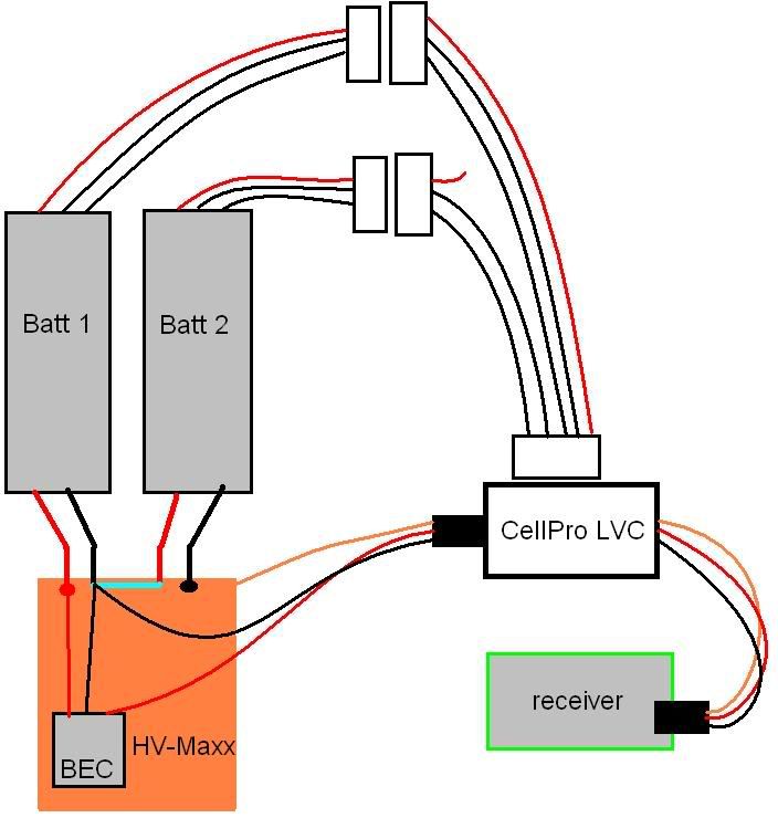
I decided to make a drawing of how this would work with the HV-Maxx, including the internal connections that the HV-Maxx uses. I am doing this because I want to see if anybody can locate a short in the system (not saying there is one, but this will help see if there is one).
 EDIT: It works the same way with the EVX. If someone wanted to overcome this issue, he/she could simply disable the BEC circuit, put a jumper on the non-BEC input, use a UBEC/receiver pack, and put the two main packs in series. Then, the ESC would work just like any other single-battery ESC out there. Here's a pic of what I mean: 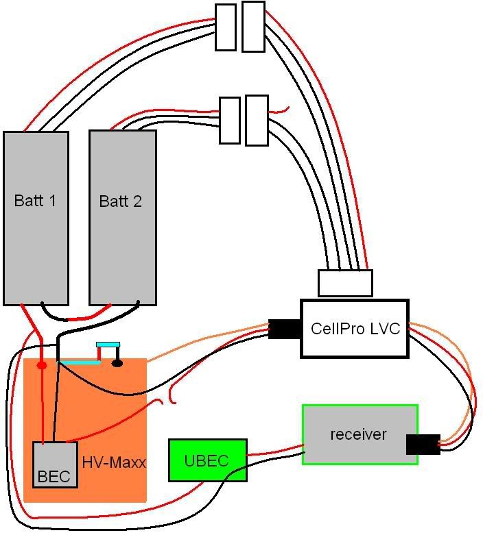
|
|
|
|
 |
«
Previous Thread
|
Next Thread
»
| Currently Active Users Viewing This Thread: 1 (0 members and 1 guests) | |
 Linear Mode

|
|

Powered by vBulletin® Version 3.8.11
Copyright ©2000 - 2026, vBulletin Solutions Inc.
vBulletin Skin developed by: vBStyles.com
Copyright ©2000 - 2026, vBulletin Solutions Inc.
vBulletin Skin developed by: vBStyles.com