

Lipo Battery Testing and Balancing |

|

|
(#1)
|
|
RC-Monster Brushless
Offline
Posts: 2,085
Join Date: Sep 2007
|
Lipo Battery Testing and Balancing -
03.02.2009, 02:26 AM
There has been alot of talk about how manufacturers/distributors come up with their C rating.
Alot of talk about how it's not standardized, and about how there isn't an established set of guidelines that sets the standards for performance. I plan on diving deeper into this and also intend to come up with my own array of test equipment. On it's way to me is this: http://www.tmenet.com/Xtrema_balancer.htm I've never seen a balancer quite like this one. I plan on running it in "computer controller mode". So I got the usb cable, a balancer plug adapter, and will be downloading the control software for windows vista. It's pretty cool because it allows the user to control and monitor the balancing process via computer. This is all fine and good, but that's not really what caught my eye. At any given time, by pressing the "test" button, it will report individual cell status and begin to graph the results. Any given time, even when the battery is under a load through the discharge leads. We all know a chain is only as strong as it's weakest link. The same goes for cells of a battery connected in series. This is where cell matching and Quality Control come into play. I intend to come up with equipment to vary the amp load on the pack being tested and monitor/graph the results. This equipment will be an ESC capable of huge amperage, probably a MMM, hooked to a servo tester as to be able to turn it up and down. The ESC will be used in brushed mode hooked to a, yet to be determined, load. In this manner, The amp load can be varied and results graphed and recorded over a time span to a preset low voltage cutout. I also have a charger that will show how many mah is returned to the pack when it is recharged. One thing I really like about this is, each cell inside the pack being tested will be shown. This will really show a manufacturer's ability to match cells. I know the entire subject of C rating is a matter of controversy. But what I intend to do is come up with a working list of test results for a number of different Lipo Brands. Something like this would at least alert us of the quality we are getting, instead of what the label "says". |
|
|

|
|
|
|
|
(#2)
|
|
Guest
Posts: n/a
|
03.02.2009, 02:48 AM
I'm currently shopping for a new charger and was going to get a Hyperion EOS0610i Net, so I can buy one now and add more later for more packs or higher S
How would one of these work as a balancing charger for charging 3 6S A123 packs? |
|
|
|
|
|
|
|
(#3)
|
|
Check out my huge box!
Offline
Posts: 11,935
Join Date: Aug 2007
Location: Slidell, LA
|
03.02.2009, 10:58 AM
Sounds interesting Sike. I will keeping an eye on your thread. I do remember someone linking an automotive battery tester that could do a variable load up to some pretty big discharge numbers. That coupled with your cell monitoring equipment would accomplish what you want. I will try to find the link, but I have no idea if it was in one of my threads or not...
Karma - not sure if i understand your question. The 610i can handle a123 cells, and will balance them. It can go up to 7s a123, if I remember correctly. I do not think you can do 3 packs at the same time though. The DUO can charge/balance 2 at a time... |
|
|
|
|
|
|
|
(#4)
|
|
RC-Monster Brushless
Offline
Posts: 2,466
Join Date: Jan 2006
Location: Florida
|
03.02.2009, 11:07 AM
We've got a couple of these here at work:
http://www.nhresearch.com/Products/4...onic-load.html I've run tests on some of our power systems to 10kW peaks with 2 of these paralleled (up to 36kW capable with 6 in parallel). For any real high power testing, a consumer oriented load just isn't going to get you there IMO. For instance, if you want to run a steady state load of 30A and then peak it to 150A for 10mS, this will do it with ease. |
|
|
|
|
|
|
|
(#5)
|
|
|
Guest
Posts: n/a
|
03.02.2009, 08:38 PM
Quote:
|
|
|
|
|

|
|
|
|
(#6)
|
|
|
Check out my huge box!
Offline
Posts: 11,935
Join Date: Aug 2007
Location: Slidell, LA
|
03.02.2009, 09:03 PM
Quote:
|
|
|
|
|
|
|
|
|
(#7)
|
|
|
RC-Monster Brushless
Offline
Posts: 2,085
Join Date: Sep 2007
|
03.04.2009, 08:52 AM
Quote:
I'm trying to keep costs to a minimum on this project. If only I had sponsership. LOL As for a "consumer oriented" load, I've been thinking about using the coils of a space heater. Possibly even 2 or 3 of them in parallel. Rewire the heater(s) to run their fans normally with house current. Then send the coil power leads out to be powered by DC. As long as the setup can handle it, all that has to be done is measure the amperage level at the battery leads. It is true that the watts of discharge is what has to be considered when sizing something like this. A space heater can go up to 1500 watts under regular household use. This would be comparable to 4S under a 100 amp load. If a 200 amp load was desired, then a 2 parallel setup would be required. For 6S testing, a 2 parallel setup would be required for testing with 100 amp load. 25.2 volts x 100 amps = 2520 watts of power. I haven't checked the resistence values or anything yet, but I'm hoping this will work. |
|
|
|
|
|
|
|
|
(#8)
|
|
|
RC-Monster Brushless
Offline
Posts: 2,466
Join Date: Jan 2006
Location: Florida
|
03.04.2009, 09:49 AM
Quote:
|
|
|
|
|
|
|
|
|
(#9)
|
|
RC-Monster Brushless
Offline
Posts: 2,085
Join Date: Sep 2007
|
03.06.2009, 12:04 AM
Still looking for a decent High Amperage Load for Testing. I have just about decided the entire space heater idea is a bad one. There's no way those wires will support the Amperage. So I'm still looking.
In the meantime, I got the balancer in and it does GREAT. It can be used along side ANY charger. So it can balance during charging. Or it can stand alone like the Blinkie. This one is better though. I love the software. With this, multiple cells and packs can be balanced to each other. In other words, pick a voltage. Let's say 4.15 volts. Then discharge each cell in a pair of 5S packs to 4.15 volts. Now the pair is ready to be ran in series with each other as a perfectly balanced 10S pack. Are these cells in balance good enough? 5mv spread. 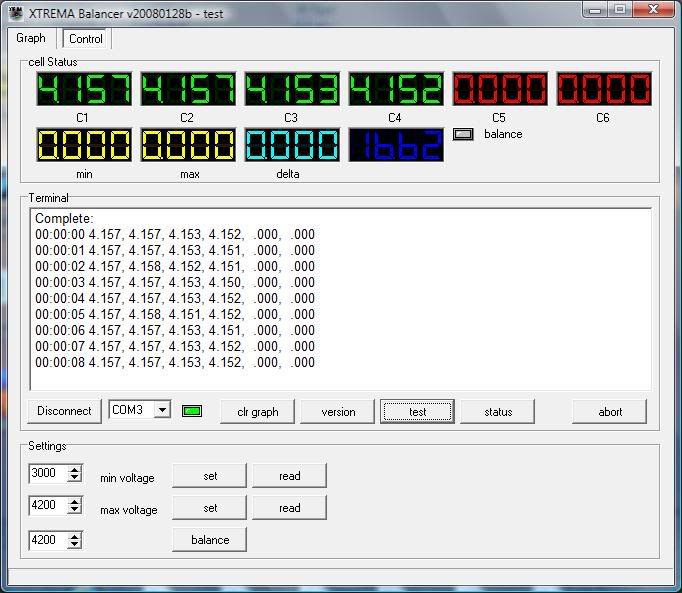
|
|
|
|
|
|
|
|
(#10)
|
|
Check out my huge box!
Offline
Posts: 11,935
Join Date: Aug 2007
Location: Slidell, LA
|
03.06.2009, 12:16 AM
Looks interesting, but it is not a charge thru desing, correct? So it will not interrupt the charge should one cell go over 4.2... Unless it is hooked into the matching xtrema charger...
I like the on screen info, should work for your uses! |
|
|
|
|
|
|
|
(#11)
|
|
|
RC-Monster Brushless
Offline
Posts: 2,085
Join Date: Sep 2007
|
03.06.2009, 12:23 AM
Quote:
With the MRC Superbrain 989, set the charging amperage to .5 This is right at the amperage the balancer discharges at. The charger is trying to charge all the cells, while the balancer is knocking the tops off the cells that have more voltage. This method takes awhile but is effective. |
|
|
|
|
|
|
|
|
(#12)
|
|
RC-Monster Brushless
Offline
Posts: 2,085
Join Date: Sep 2007
|
03.06.2009, 11:08 PM
I was just sitting here and it hit me!
 The DC load that will be used is Electrolysis. I already have one made with a Stainless Steel plate configuration of 4S2P. I built it with the intention of installing it on my Blazer to improve the fuel Mileage. Did my homework on varying the amp draw by using a ratio of Sodium Hydroxide and Water. The amp draw and Gas output is quite low without adding something to increase the conductivity of the water. PWM is normally used in conjunction with this to limit the amp draw. SO..........with an increase in the concentration of Sodium Hydroxide AND the use of an ESC to turn it up and down, shazam!..........DC load capable of big amp draws. Big Amps thrown at a Hydrogen unit will normally boil the water in time. Since rarely, 30 minutes at a time will be exceeded with testing, this should do. The product of Electrolysis is Hydrogen and Oxygen. It breaks down water into it's elements by breaking the covalent bond of the atoms. Hydroxy gas is VERY explosive. I'll just vent it to the outside. Ok, now that we have established a good working DC load, we need a good heavy duty amp meter. Something that will accurately measure up to ummmmmmm............let's say 200 amps. I wonder if I can find one of those digital types that work with a shunt? |
|
|
|
|
|
|
|
(#13)
|
|
RC-Monster Aluminum
Offline
Posts: 905
Join Date: Aug 2007
|
03.13.2009, 02:04 AM
Nice idea for the load! How big of a tub do you plan to use?
Have you decided on some standards for the testing? Temp, voltage, and capacity requirements for 1c vs stated capacity maybe? |
|
|
|
|
|
|
|
(#14)
|
|
|
RC-Monster Brushless
Offline
Posts: 2,085
Join Date: Sep 2007
|
03.13.2009, 06:48 PM
Quote:
The Hydrogen Generator that I built resides inside a 18" long stick of 4" pvc. It works best vertically. Gas rises to the top and exits through a screw in fitting to a secondary bubbler. This also "lifts" water along with it into the secondary bubbler. Water from the secondary bubbler travels back down into the bottom of the Hydrogen Generator chamber through another tube. In other words, as water is lifted out the top with the gas, water is replaced into the bottom. It circulates and the Hydrogen/Oxygen of course rises to the top of the bubbler. The bubbler is useful in extracting water vapor from the gas, and also helps prevent flashback to the generator in case something goes wrong. There is some question in my mind about just how many amps this setup can maintain. I know raising the concentration of sodium hydroxide will inherently raise amp draw, BUT..........once you have so many bubbles forming on the plates it becomes a limiting factor. The bubbles begin to insulate the plates because they can't get off there quick enough. LOL I'll have to put this to the test. Thinking back, I remember directly hooking a 4S lipo to it, and it was getting a rubber insulated 14Ga. wire REALLY hot. It would have melted the wire if I would have left it hooked up. Of course, silicone wire doesn't do this. I would like your input concerning standards of testing. To be fair to each brand, conditions have to be controlled. One thing that I DON'T aggree with: In all the testing methods that I've observed, they always hook the test equipment directly to the tabs on a single cell. That's NOT where we hook our stuff.  We hook our ESC's directly to the power connector on the pack. This makes our setups work with the resistence in the wiring. Most packs "only" come with 12Ga. wire on them. At 100+ amp load, resistence in 12Ga. wire becomes a factor.If a PACK is rated with a certain C rating, shouldn't that PACK deliver that C rating? I think so. One thing about standards I believe, it should be the PACK tested at the connector that determines C rating. Any thoughts or suggestions? |
|
|
|
|
|
|
|
|
(#15)
|
|
RC-Monster Aluminum
Offline
Posts: 905
Join Date: Aug 2007
|
03.15.2009, 06:27 PM
While a true rating of the pack certainly depends on the wire and all resistances involved, cells are just rated by themselves for simplicity. I would like to see both side by side actually, to get an idea of how big a difference wiring and plugs can make on heat or capacity.
Some standards I had considered before, taking ques from TP testing and enerland quality standards: Continuous rating capacity within 10% of 1C discharge capacity. Continuous rating limited to 50*c cell temperature with ambient temp of 25*c- no cooling air flow Capacity cutoff at 3v/cell Continuous amp draw should not draw cell below 3.2v until 80% of capacity is spent (off the cuff starting point) Cells should all start at 25*c temp As we know, internal resistance drops with increased cell temp, so controlling and recording this aspect is very important. A cell that shows a greater increase in temp over discharge will have a higher resistance too. The steepness of the discharge graph will show how well the voltage is held through the cycle. Some inferences we could make Lower quality cells will heat up more Lower quality cells will have a steeper discharge graph LQC will not hold 90% capacity under higher discharges LQC will not hold as high of voltage under high discharge Once enough cells are tested, standards can be set for quality that quantify the averages and the standard deviations from the norm. Then we can simply use statistics to pick out where a cell is lagging- such as voltage under load or capacity. |
|
|
|
 |
«
Previous Thread
|
Next Thread
»
| Currently Active Users Viewing This Thread: 1 (0 members and 1 guests) | |
 Linear Mode

|
|

Powered by vBulletin® Version 3.8.11
Copyright ©2000 - 2025, vBulletin Solutions Inc.
vBulletin Skin developed by: vBStyles.com
Copyright ©2000 - 2025, vBulletin Solutions Inc.
vBulletin Skin developed by: vBStyles.com