


|

|
(#31)
|
|
RC-Monster Mod
Offline
Posts: 6,741
Join Date: Jul 2005
Location: VA in the US
|
09.19.2005, 11:29 AM
That is nice. I hope mine turns out that good. Would it have been better to put the aluminum to the outside. Help protect batteries better and keep them on buggy to. Just a thought.
|
|
|

|
|
|
|
|
(#32)
|
|
RC-Monster Mod
Offline
Posts: 5,297
Join Date: Mar 2005
Location: SoCal
|
09.19.2005, 06:31 PM
I could have put the aluminum angle on the outside, but then the vertical part of the angle pieces would be off the chassis, which could reduce the advantage of having them on the chassis. To protect the batteries, I will be putting the mud guards back on, and I am thinking of getting some polycarbonate angle and using that to protect the edge of the batteries, and also to provide better battery mounting. I will see if I can find the correct angle pieces first.
|
|
|
|
|
|
|
|
(#33)
|
|
RC-Monster Mod
Offline
Posts: 5,297
Join Date: Mar 2005
Location: SoCal
|
01.07.2006, 12:28 PM
It's been almost 4 months since I have updated here! My buggy has gone through a modified chassis from the last picture, and just recently I made another new chassis to accomodate my LiFePO4 batteries.
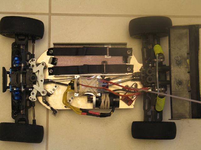 This is an overall picture of the buggy. You can see the servo mounts (in front of motor), but with no servo. 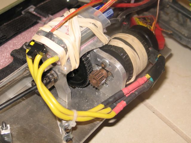 Here you can see all of the electronics (or would, if I had a servo). On top of the center slipper clutch support is a MGM Compro 12012 (yes, it did finally come back). I have it on 2 layers of foam and secured by rubber bands for a tight fit that will allow some movement in the event of a bad crash or hard landing. You can also see the motor, a Feigao 540C 9L. The mount for the motor is new, and mounts to the chassis using 3 screws, and is secured to the top plate using 2 screws. The front bearing support is screwed into the chassis with 2 screws, and also to the top plate with 2 screws. The rubber bands around it are for mounting an external BEC, and I will be getting this one: http://www.xushobby.com/servlet/Detail?no=38 Also visible is the receiver, which is mounted using velcro. To the left of the receiver is the antenna mount, and you can just barely see the white of the antenna tube. 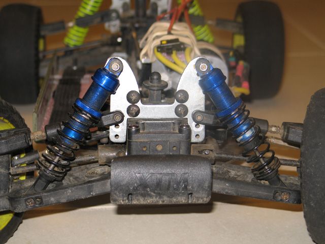 These "front" shocks replaced the older ones that didn't look as good and were broken. I say "front" because they are actually the shocks for the rear of the buggy (from when I bought it), but they give just as much travel as the stock front shocks. The reason why the preload is like that is because I am also using the stock front springs, which are (obviously) shorter than the rear springs. I need to get some stiffer springs for the front, though. 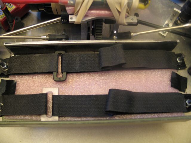 A close-up of the battery mounting. Those velcro straps are custom made. The black piece that connects one of the straps was found on the ground, and since I didn't have another one, I made one from polycarbonate. You can also see the use of a foam pad, which is there to provide a small amount of shock absorbtion. You can also see how I attached the front and rear chassis braces (the turnbuckle things) to the aluminum angle piece that is used for battery mounting. 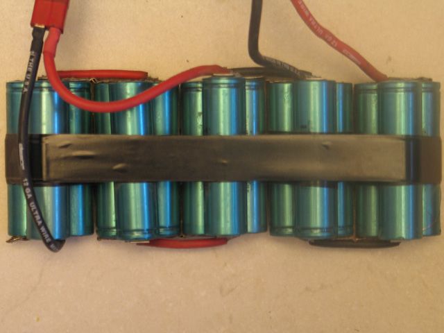 This is the (famous) LiFePO4 that I have been talking about for so long. It is comprised of 15 cells total (3.2v 1200mah), and there are 5 blocks of 3 cells in parallel (5 groups of 3.2v 3600mah) that are put into series (so 16v 3600mah total). This pack weighs about 150grams less than 12 NiMh cells, yet will perform like 14 NiMh cells or better. The construction of the pack has the nickel strips soldered together, and between each 3cell group there is a wire to give greater amp-handling capabilites (these wires are put on like they would be for a side by side NiMh pack). There are 2 sets of power leads coming from the pack because my charger (Duratrax ICE) can only charge up to 4s Li-Ion (this pack is being charged as Li-Ion), so I split it up into a 3s and a 2s. The whole pack is put into series by a series adpater. 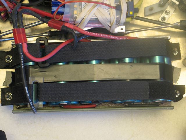 And here is the battery mounted, snug as a bug in a rug :). The battery isn't going anywhere unless the battery straps decide to rip. They say a picture is worth 1,000 words, and in this case that is true! Sorry for the lower-than-expected quality of the pictures, I couldn't get the lighting right. The next things that I will do include: -Put some sort of mud guard on the left (motor) side of the chassis to prevent crap from getting into the motor and receiver. -Cut and drill holes in the chassis to remove weight. -Get a new servo and UBEC. -Get stiffer front springs. |
|
|
|
|
|
|
|
(#34)
|
|
RC-Monster Mod
Offline
Posts: 5,297
Join Date: Mar 2005
Location: SoCal
|
01.10.2007, 11:57 PM
Damn, it has been over a year...
Let's just say the X-T looks nothing like that anymore besides the front and rear ends. I went back to the stock chassis and made a new motor/diff mount setup that puts the motor in the front-left corner. I had been driving this buggy with Maxamps 4s 6300mah (2100HV cells), but one parallel group puffed up. So I sent the pack back to Maxamps, and Austin verified a complete pack replacement. However, when I got it back, only the puffed up group had been replaced (I even included a detailed letter and references). So, I hacked up that battery pack for the loose cells, since I didn't want to deal with it any more. The buggy has just been sitting on a shelf for the past few months, waiting for a battery. I think I'll let it share the 5s2p A123 pack from the Revo) for some insane power. I have some pics from a while ago that show it in its current form: 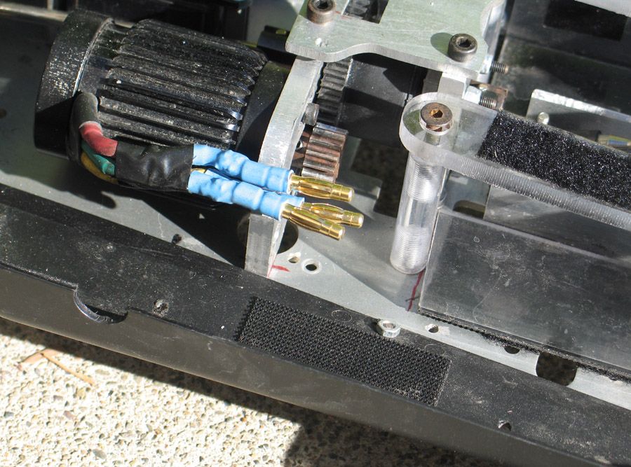 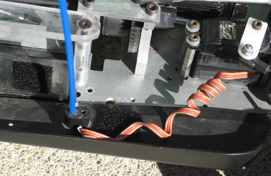 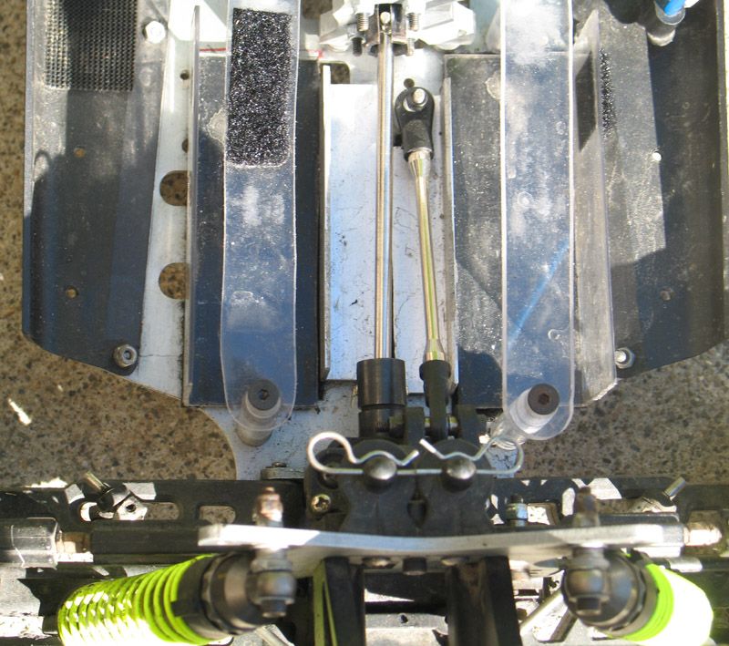 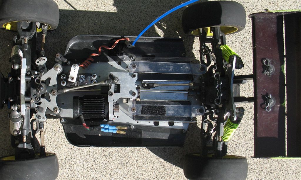 The battery mounts shown were for the 4s 6300mah pack, but I'll remove those when I work on the buggy again. |
|
|
|
 |
«
Previous Thread
|
Next Thread
»
| Currently Active Users Viewing This Thread: 1 (0 members and 1 guests) | |
 Linear Mode

|
|

Powered by vBulletin® Version 3.8.11
Copyright ©2000 - 2025, vBulletin Solutions Inc.
vBulletin Skin developed by: vBStyles.com
Copyright ©2000 - 2025, vBulletin Solutions Inc.
vBulletin Skin developed by: vBStyles.com