


Thoughts on Controller Longevity Design |

|

|
(#1)
|
|
RC-Monster Brushless
Offline
Posts: 2,085
Join Date: Sep 2007
|
Thoughts on Controller Longevity Design -
09.11.2009, 01:08 AM
Today at work, I dissected an overheating Brushless Controller for one of our larger double pallet jacks. This uses a 24 volt Lead acid battery. (750 amp hour)
This controller is rated for 24 to 36 volt duty and has a 400 amp capacity. We were doing amp draw tests, since the leads were fried going to the motor. In fact, everything was getting hot and something was thermaling, causing it to shut down. Using an Amp Clamp with the drive tire off the ground, amp draw would spike to the 70 range on acceleration, then taper off to about 36 amps at top speed. The motor in use is a brushless AC induction motor rated at 3.3kw. I brought two of the cards home from the controller, since we replaced this one with a new unit. I did not bring the main brain board. The Power card (FET Board), and another board that houses 22 - 1200uf low esr caps rated for 50 volts. This board also has current detecting hardware. We felt like 36 amps was alot to be running at no load. (864 watts) The Drive Tire needed replaced anyway, so the forklift Tech I was working with decided we should do a test under a load. He let the jack down, placed the drive tire on the floor, got up against something solid and opened up the throttle. Didn't take long before we could smell what was left of the drive tire getting hot and starting to smoke, but the interesting part was.......... This controller limits the amp draw to 400 amps. Amp drawn spiked up to 350 amps, then rose on up to about 395 amps and stayed there for the duration of the test. My Question is: Is it the cost factor and complexity of the Hardware and Firmware the prohibits using this type of setup in our Brushless ESC'S? This would add to the longevity a GREAT deal and cure alot of other problems as well. Give me some thoughts guys. I hope Castle responds to this. But in the meantime, check out these boards. Notice the two round components on the first board? Current Detection. 2 of the Motor Leads come up through these, the 3rd Motor lead has nothing.  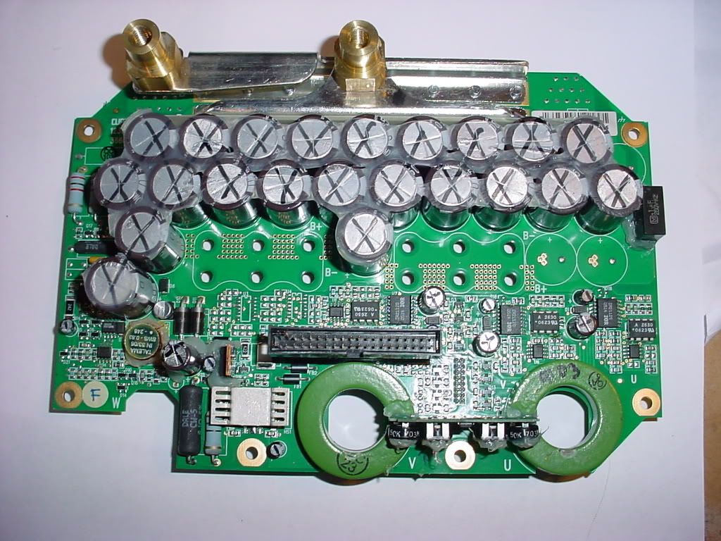 Here's the FET Board. Remember, 24 to 36 volt operating range at 400amps. This setup does use regenerative braking. 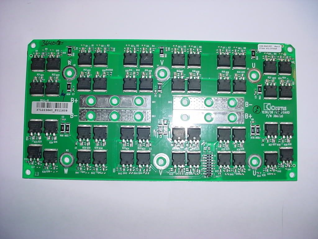
|
|
|

|
«
Previous Thread
|
Next Thread
»
| Currently Active Users Viewing This Thread: 1 (0 members and 1 guests) | |


 Threaded Mode
|
|

Powered by vBulletin® Version 3.8.11
Copyright ©2000 - 2026, vBulletin Solutions Inc.
vBulletin Skin developed by: vBStyles.com
Copyright ©2000 - 2026, vBulletin Solutions Inc.
vBulletin Skin developed by: vBStyles.com