

Power Supply Conversion Questions (56K beware) |

|

|
(#1)
|
|
Never Fast Enough
Offline
Posts: 914
Join Date: Jul 2005
Location: UT
|
Power Supply Conversion Questions (56K beware) -
10.04.2007, 07:03 PM
I bought this 30A 12V power supply off of eBay. It came with all the parts to be converted for R/C charging use, but it didn't come with instructions. I've contacted the seller, but haven't received a response. I've also searched the net, but I've only found places selling them.
I'm hoping some of you mega-smart people can help me out. I'm handy with a soldering iron, but I'm just not sure exactly where to start. Here are some pics. PIC 1  PIC 2 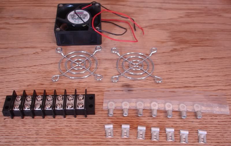 PIC 3  PIC 4 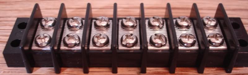 PIC 5 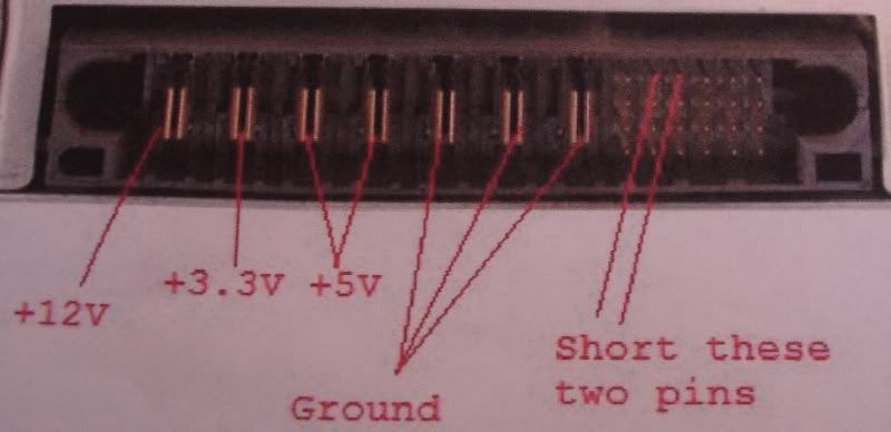 PIC 6 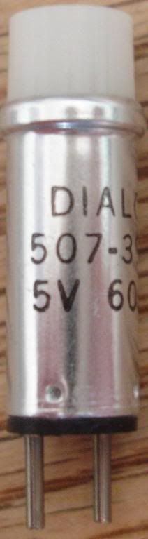 PIC 7 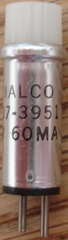 PIC 8 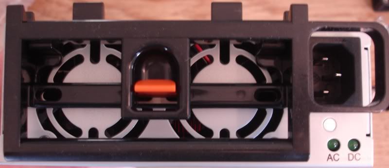 PIC 9 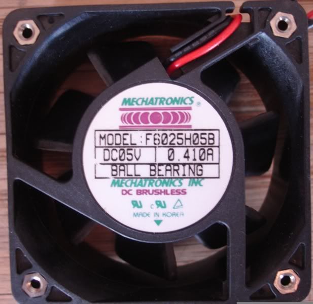 The pics are a little large on purpose for the detail. There are 7 of each connector, but which ones go where? Also, what is the small metal cylinder with the two prongs and where should it go? Thanks in advance for any and all help you can give! Brian |
|
|

|
|
|
|
|
(#2)
|
|
RC-Monster Admin
Offline
Posts: 14,609
Join Date: Nov 2005
Location: Des Moines, IA
|
10.04.2007, 08:21 PM
OK, first of all, I edited your post to number the images to make the following explanation easier to understand. I hope you don't mind...
The leftmost connector in pic 3 is probably meant to slide onto the connectors in pic 5. The rightmost connector in pic 3 is probably meant to attach to the terminal block in pic 4. So, you somehow mount the terminal block (pic 4) to the case near the output strip (pic 5). Then, make some short jumpers with the leftmost connector type (pic 3) on one end and the rightmost connector type on the other. Since there are two screws on the terminal strip (pic 4), you use one from each pair for the jumper wire, and the other screw to go to whatever you plan to hook this to (charger?). Since the fans are 5v, you use the 5v line and ground for those. You won't be using the 3.3v line unless you have a use for it somehow, or can use that line to add a load resistor to help regulation (assuming that the 3.3v line is used for that purpose - it could also be the 5v line). To short the two pins, see if you can find a spare computer harddrive master/slave jumper. That should fit onto the pins in question. I have no idea what those cylinder things are. They don't look like caps. I would leave those unconnected for now until you get the instructions. |
  |
|
|
|
|
|
(#3)
|
|
Never Fast Enough
Offline
Posts: 914
Join Date: Jul 2005
Location: UT
|
10.04.2007, 08:35 PM
Thank you immensly!
It totally makes sense now. It actually came with a jumper for those two pins, so that's in good shape now. I learned that the cylinder thing is a 5V light that will indicate when the power is on. It's unnecessary though because the internal fans are always on when the ps is on. Would you bother soldering the flag type connectors (leftmost in pic 3) to the connectors in pic 5, or will a pressure fit be sufficient? Will one ground lead be enough to get the full 30A, or would it be better to double up the ground wire. This will be powering my new Hyperion 1210i when it arrives. I think it will work great. Thanks again for your help! |
|
|
|
|
|
|
|
(#4)
|
|
RC-Monster Admin
Offline
Posts: 14,609
Join Date: Nov 2005
Location: Des Moines, IA
|
10.04.2007, 08:48 PM
Wellll, if it were me, I wouldn't use any of that stuff. I'd use these and do the wiring on the inside of the case. Maybe even use a pair for two chargers.
But, using those parts, I would solder the wire to the connectors and just press fit them to the output strip. If they are not tight, I'd come up with some other way, but that's just me. |
|
|
|
 |
«
Previous Thread
|
Next Thread
»
| Currently Active Users Viewing This Thread: 1 (0 members and 1 guests) | |
| Thread Tools | |
| Display Modes | Rate This Thread |


 Linear Mode

|
|

Powered by vBulletin® Version 3.8.11
Copyright ©2000 - 2026, vBulletin Solutions Inc.
vBulletin Skin developed by: vBStyles.com
Copyright ©2000 - 2026, vBulletin Solutions Inc.
vBulletin Skin developed by: vBStyles.com