

Possible slipper idea?? |

|

|
(#1)
|
|
RC-Monster Admin
Offline
Posts: 14,609
Join Date: Nov 2005
Location: Des Moines, IA
|
Possible slipper idea?? -
10.23.2006, 09:50 PM
OK, don't laugh!
I was looking at my H8 with the "prototype" motor on it using the clutchbell and started to think of an idea about making a compact slipper for buggies using the clutchbell (or something similar). I mean, a Nitro engine uses the clutchbell as a reverse slipper really. You just have the make it so the clutch applies pressure all the time but allows to slip when needed instead. It would be nice to have a compact slipper setup for use with centerdiffs. After some measurements, I came up with something to start with: Cross-section view of CB slipper Excusing the crude drawing (using Excel with some Paint Shop Pro touch-ups); basically you have the clutchbell (black) that is coupled to the center shaft by the spring loaded slipper pads (blue) pressed into the inside of the bell via the springs. Since the motor shaft is not long enough to extend to the needed depth, an extender is used. This design allows you to still slide on the bearings (green) and is held with grub screws (purple-ish). Yeah, it looks dumb and there are some flaws to this design. But I think there might be some merit to it. The biggest problem is to get the shaft extender to fit inside the CB opening and still use bearings. Even using 6mm X 10mm bearings (for the largest inside opening), there is only 1/2 a mm for the "walls" of the extender at one point since the motor shaft is 5mm in diameter. If the CB opening could be bigger, the extender should work. Anyway, it's just an idea, so be gentle! :dft001: |
  |

|
|
|
|
|
(#2)
|
|
Guest
Posts: n/a
|
10.23.2006, 10:04 PM
Ive always had my Nitro sniffing mates telling me they don't need a slipper, because the clutch takes the strain off somewhat.
being a soft link to the transmission it is. I have wondered about utilising a clutch system myself. are you going to build it Brian? |
|
|
|
|
|
|
|
(#3)
|
|
RC-Monster Admin
Offline
Posts: 14,609
Join Date: Nov 2005
Location: Des Moines, IA
|
10.23.2006, 10:12 PM
No, I'm not going to build it. I don't have the tools (or cash) to attempt something like this. I'm just trying to throw ideas out there in the hopes someone with the time, capital, and tools wants to try it. Or at least maybe inspires something else that might work.
It just would be nice to have options. Mike will have the slipperential out shortly (??), but that looks like it's more for custom applications or using the GMaxx chassises (or is that "chassi"?). Other applications can use the Revo-style, Strobe, or Robinson Racing slippers. Buggies tend to be a little short on room and the center diff doesn't leave much room for any of those. |
|
|
|
|
|
|
|
(#4)
|
|
RC-Monster Mod
Offline
Posts: 5,297
Join Date: Mar 2005
Location: SoCal
|
10.23.2006, 10:22 PM
You should see if Mike would be able to make it just for testing. It would certainly be an alternative to the slipperential, with less weight and complexity.
At one point I had the idea to make a slipper-diff in place of the center diff. It would have a custom spur gear mount (in place of the Hyper 7/8 spur gear) that would have a slipper clutch built into the back of it. Some time I should attempt to draw it up in Solidworks. |
|
|
|
|
|
|
|
(#5)
|
|
Guest
Posts: n/a
|
10.23.2006, 10:29 PM
I think he has idea's for a Truggy/buggy 'slipperential' (begging for a trademark)
As winters coming, lets hope he has some more 'Lab time' as I have a CRT/Jammin just waiting for it. and yes it is ist's chassis :dft012: |
|
|
|
|
|
|
|
(#6)
|
|
RC-Monster Admin
Offline
Posts: 14,609
Join Date: Nov 2005
Location: Des Moines, IA
|
10.23.2006, 11:21 PM
MM: I'd like to see your idea for the slipper on the center diff. If it would fit in between the stock diff mounts, that would be nice.
I was just trying to come up with some type of "bolt-on" part that was small and easy to fit. A little outside the box maybe... |
|
|
|
|
|
|
|
(#7)
|
|
RC-Monster Mod
Offline
Posts: 5,297
Join Date: Mar 2005
Location: SoCal
|
10.24.2006, 12:39 AM
It wouldn't fit inbeween the stock diff mounts, since it attaches to the plastic diff housing and extends away from the diff. In some cases, it might be the right size so that the shorter center-front dogbone could replace the longer center-rear dogbone, assuming that your buggy works like that (my XTM-Xterminator does).
Your idea would certainly be the easiest bolt-on slipper out there (you would literally bolt it on :) ). It's an interesting idea, something I had never seen before. It would be nice if someone could experiment :). |
|
|
|
|
|
|
|
(#8)
|
|
RC-Monster Admin
Offline
Posts: 10,480
Join Date: Feb 2005
|
10.24.2006, 01:57 AM
It is an idea, but i think it will be too expensive to have in production Brian.
And you will have the problem again with wearing pinion. Less because of the slipper, but still. And i doubt if .5mm of thickness is enough |
|
|
|
|
|
|
|
(#9)
|
|
Custom
Offline
Posts: 124
Join Date: Mar 2006
Location: Michigan
|
10.24.2006, 09:48 AM
You could push the slipper out farther so that the motor shaft is not in the clutch bell gear. That would solve the wall thickness problem. You could also flip the clutch bell around. This would cause a clearance issue with the setup you show but you solve that by flipping the diff. around (at that point the gray shaft might have to be extended a little).
|
|
|
|
|
|
|
|
(#10)
|
|
RC-Monster Admin
Offline
Posts: 10,480
Join Date: Feb 2005
|
10.24.2006, 12:08 PM
That wouldn't help really. you don't want the pinion to stick out too far. And besides, i think it will be allmost impossible to get a proper resistance on the slipper at those high RPM's it's running on. (low torque/ high rpm is hard to build a slipper on)
|
|
|
|
|
|
|
|
(#11)
|
|
RC-Monster Mod
Offline
Posts: 4,217
Join Date: Apr 2006
Location: Chicago, IL
|
10.24.2006, 01:15 PM
Why couldn't you just mount a typical 3 shoe nitro clutch on the shaft of the motor. You woulnd need an adaptor of some sort, but sesides not being able to use the motor to brake, what is wrong with just using a standard nitro clutch?
to make it... or break it... Silent...But Deadly |
|
|
|
|
|
|
|
(#12)
|
|
RC-Monster Admin
Offline
Posts: 14,609
Join Date: Nov 2005
Location: Des Moines, IA
|
10.24.2006, 03:33 PM
I don't think a standard shoe clutch design would work well for two reasons:
1) The clutch engages only at a certain rpm to allow the engine to idle without stalling. We don't need that with electric for obvious reasons. Another function of the clutch is to allow engine rpms to rise enough where it develops some usable power. Again, this isn't needed for electric. 2) The centrifugal force pushes the shoes into the bell harder and harder as rpms increase effectively locking it. High rpms is where you want the protection. The stock setup will grip the hardest at the high rpms and will offer virtually no slip. I wanted a slipper with an even amount of slip no matter what rpm it is spinning at. Flipping the diff and mounting CB in the standard way sounds like the best idea so far. I'll work on a V2 when I get home and post the result. Thanks for the feedback guys! |
|
|
|
|
|
|
|
(#13)
|
|
RC-Monster Admin
Offline
Posts: 14,609
Join Date: Nov 2005
Location: Des Moines, IA
|
10.25.2006, 10:35 PM
OK, here's the same basic idea with the CB facing the "right" way. I didn't touch this up in PSP though, it's just a direct Excel screenshot (OK, I was lazy). This one is nicer in that there is not thickness problem, and you can use regular 5X8mm bearings. Securing the motor shaft might be a little hard to go to though - maybe a small hole in the CB to allow an Allen wrench to get in there?
|
|
|
|
|
|
|
|
(#14)
|
|
RC-Monster Mod
Offline
Posts: 4,217
Join Date: Apr 2006
Location: Chicago, IL
|
10.25.2006, 11:42 PM
looks better that way. how do you adjust the tention?
to make it... or break it... Silent...But Deadly |
|
|
|
|
|
|
|
(#15)
|
|
RC-Monster Mod
Offline
Posts: 4,217
Join Date: Apr 2006
Location: Chicago, IL
|
10.26.2006, 12:26 AM
What about moving the slipper pad to the flat inner face of the clutch bell and using a conventional spring and nut to adjust slipper tention.
Something like this. 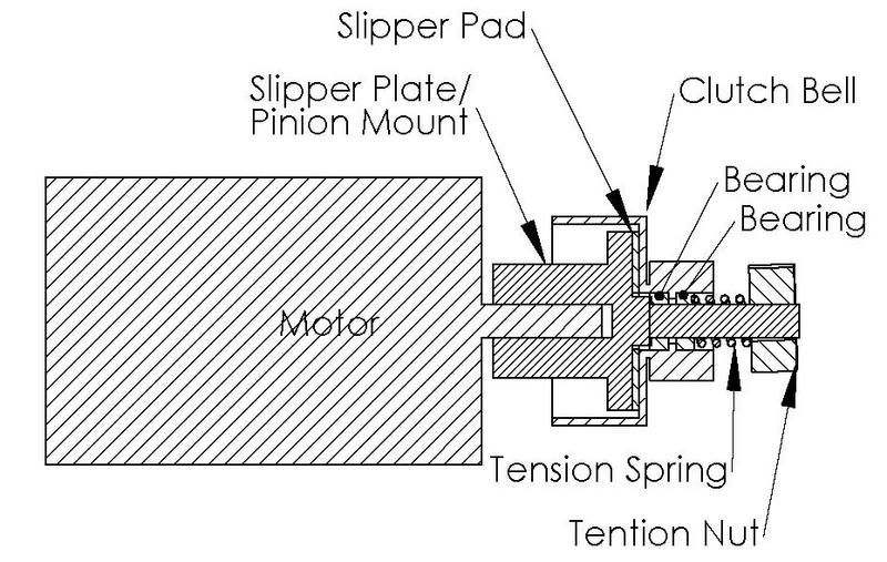
to make it... or break it... Silent...But Deadly |
|
|
|
 |
«
Previous Thread
|
Next Thread
»
| Currently Active Users Viewing This Thread: 1 (0 members and 1 guests) | |
| Thread Tools | |
| Display Modes | Rate This Thread |


 Linear Mode

|
|

Powered by vBulletin® Version 3.8.11
Copyright ©2000 - 2026, vBulletin Solutions Inc.
vBulletin Skin developed by: vBStyles.com
Copyright ©2000 - 2026, vBulletin Solutions Inc.
vBulletin Skin developed by: vBStyles.com