

|
|

|

|
(#1)
|
|
Guest
Posts: n/a
|
04.05.2009, 07:29 PM
I am running 10s with a 1515/2y in a Losi 8t and it was a big improvement over the 2.5d and 6s I was running. Iam using 2 5s 3700 packs this setup is too heavy I wany to run 5s 2500 packs to get the battery weight under 650 grams right now its at 950
Iam using the Hv110 ESC with a pistix adapter and it is as smooth as any MMM with the recent firmware and software upgrades, the only problem is no reverse or brakes |
|
|

|
|
|
|
|
(#2)
|
|
KillaHurtz
Offline
Posts: 2,958
Join Date: Apr 2006
Location: Bucks Co, PA
|
04.05.2009, 10:01 PM
BTW.. I had a 2Y on 8s w/ the MGM before in my Revo, was really nice and was always stone cold. Always wanted to do the 10S, but only ever got one run of 12S A123. It was pretty bonkers.
FLydma.com still has some 5S 2500 30C packs FS, $50ea. I have 2s and 4S of these for my .5, these are great batts at great prices. Def check it out. |
|
|
|
|
|
|
|
(#3)
|
|
|
Guest
Posts: n/a
|
04.05.2009, 10:18 PM
Quote:
thanks for the heads up on the 5s packs, though they are too fat for my battery tray...I did end up buying a couple from True Rc that were 138x43x25, I did but one 5s 2500 pac from Mike ...thats all he had...the price Diversity had though was GREAT...I ll never beat that price!! my tray measures 165mm x 52mm |
|
|
|
|

|
|
|
|
(#4)
|
|
KillaHurtz
Offline
Posts: 2,958
Join Date: Apr 2006
Location: Bucks Co, PA
|
04.05.2009, 10:10 PM
That reminds me... One bad thing about doing the CD conv is that you lose the tranny reduction ratio. I have 2.89 Cen diffs now, and I couldn't really find a ratio that would work. I would have to use other diffs.
|
|
|
|
|
|
|
|
(#5)
|
|
|
RC-Monster Aluminum
Offline
Posts: 517
Join Date: Jul 2006
Location: Utah
|
04.06.2009, 12:26 AM
Quote:
|
|
|
|
|
|
|
|
|
(#6)
|
|
KillaHurtz
Offline
Posts: 2,958
Join Date: Apr 2006
Location: Bucks Co, PA
|
04.06.2009, 11:48 AM
I thought about putting the motor right on top, and its an easier thing to design, but I decided to make it offset so that the CoG was a bit lower from dropping the motor a couple cm, and also to keep the motor on one side to save room for the steering servo and maybe radio mount on one side opposite of the motor.
Neu motors are 44mm(?) in diameter, so at worst it only leaves 30mm of extra space between the TVPs. Obviously you are going to loose the oem radio box if the motor goes fwd, so I had planned on using an FLM radio tray plate, and removing material that would interefere (or making my own.) This plate does sit somewhat high, and it incorporates the uppermounts for the str servo rack. The lower and more offset you can get the motor, the more room it leaves for the plate. I think if you managed to get the motor level w/ the CD, the motor would fit under plate, as that is not possible, if I have to raise the motor some, then perhaps I would only have to trim away 25-30mm from the plate. That leaves quite a bit of room for a str servo, and even a radio box, or even esc, if you could tuck the servo underneath the plate. I attached a really crappy drawing illustrating what I mean. If you plant the motor right above the CD, you loose almost all this space, the motor sits high, and/or you have to sit the CD well to the side and have drivelines at unhappy angles. Lastly, I know you can get pretty big spurs, but, big spurs take up lots more of the limited space between the plates, and more importantly, the stick out far underneath the CD. The CD will already sit quite a bit higher than the F/R diff outputs, so the bigger the spur, the higher it needs to sit to not have the spur hanging it nuts out the bottom of the truck. Ideally a very small spur would be used so the CD could be mounted low and at more optimum angles for the drivelines, and make up the FDR by low gearing in the diffs, say 4.2s or whatever as in truggy diffs. For may particular intent, I think I need a 15-17:1 FDR, which is next to impossible w. Cen 2.89s and a CD. At worst take it upto about stock ratios on the diffs, and use Mike's 50T spur on the slipperential w/ 10T pinion. Better yet would be 4.2 or so diffs, Mike's 46T and a 11T+ pinion. |
|
|
|
|
|
|
|
(#7)
|
|
|
RC-Monster Aluminum
Offline
Posts: 517
Join Date: Jul 2006
Location: Utah
|
04.06.2009, 01:23 PM
Quote:
|
|
|
|
|
|
|
|
|
(#8)
|
|
RC-Monster Mod
Offline
Posts: 5,297
Join Date: Mar 2005
Location: SoCal
|
04.06.2009, 02:37 PM
Finnster, I like that Savage layout a lot... Should allow both batteries to sit inside the FLM extended low CG TVPs as well. Only thing is, I wouldn't incorporate the servo mounts into the upper deck as I am using the FLM servo mounts which IMO would be a simpler option.
Have you considered designing a CD mount similar to what I have on my Savage? This is just about the strongest way to do it (from what I have found), because it incorporates the motor and center diff into the chassis, which also strengthens the chassis. The skidplate method is definitely easier, but the attachment points for the skidplate are few and far between, and you will lose some chassis strength as well. Last point, if you go with a Slipperential, I can pretty much guarantee you won't have any issues with the Flux diffs. This means you could go back to the original diff ratio and use the 46t gear. |
|
|
|
|
|
|
|
(#9)
|
|
KillaHurtz
Offline
Posts: 2,958
Join Date: Apr 2006
Location: Bucks Co, PA
|
04.06.2009, 05:08 PM
@ p4: Do you have a pic of your setup to show what you mean? I'm taking it you made basically a 1spd tranny? (sort of like the kershaw DD unit, but hopefully less craptacular lol) An idler gear would def help getting the ratio down a bit, lend flexbility to the geometry, but its a bit more complicated unit to get together and beyond was I was thinking of doing.
MM: It is a better design. My first designs were to have the motor mount directly attach to the tranny mount holes, but I was having problems calculating exactly where those holes were. I actually went so far as to buy a used geometry textbook that was @ the library for $0.50 lol. I could measure all the lengths between the holes easy enuf w. a caliper, but what I was having a hard time determining was the angles between the holes. Its a pita to calc angles when you don't have a 90* angle, and its been forever since i've done geometry. I know there was something simple I was missing. Ie, are the upper and lower holes directly underneath ea other and perpendicular to the ground, as well as parallel top line to bottom line? IOW, could you draw a big 90 between 3 sets of holes. It didn't seem like you could, but I really need to go back and look. I know the rear upper tranny mount is not perp to the lower mount, and I couldn't verify the front one. The tranny mount is somewhat asymetrical, and I wouldn't want to assume they do run perp, then to create a mount and find out its pitched forward or backwards one way or the other. Also, What I was considering was reducing the number of mounts that need to be machined and designed. if the motor mount could be made in a dimension the same as a popular plastic mount (say a losi 8) then only one mount would need to be made, then use the plastic part for other side. Its a bit cheaty, but I didn't want to draw a whole other mount and worry about the geometry issues. If I had a CNC or even a drill press to hand machine parts that would be one thing, but trying to draw up a CAD file on a cheap freeware SW, then send it to someone to build, then get it back to see I fragged up a measurement and it doesn't fit sucks. Lastly, I wasn't sure this would leave enough room in back for batts as the tranny was pretty well centered. I would hope to move it up some, and maybe where I could use an OEM driveshaft. Less custom stuff to drive price and headaches higher. I'll have to go home and look at my notes from a while back and see what I knew. |
|
|
|
|
|
|
|
(#10)
|
|
|
RC-Monster Aluminum
Offline
Posts: 517
Join Date: Jul 2006
Location: Utah
|
04.06.2009, 05:29 PM
Quote:
BTW, you are right about e-machineshop being hideously expensive. I ended up just getting the parts waterjet cut (hence the raw finish) and having a local machinist counterbore for the bearing recesses. If i were to ever be in a production situation like Mike, the machined finish would be important for sales, but for functionality it does nothing. If you want, I can submit any drawing you want to my waterjet place when I have other work for them (cheapest I've found). If you want any dimensions on what worked for me as well, just ask. |
|
|
|
|
|
|
|
|
(#11)
|
|
KillaHurtz
Offline
Posts: 2,958
Join Date: Apr 2006
Location: Bucks Co, PA
|
04.06.2009, 05:14 PM
BTW, I do have a set of those FLM servo mounts as well. Those were an alt plan on mounting the str servo. Ideally underneath the plate, leaving the space on the plate open to mounting all the electronics.
I could mount the servo flat up against the bottom of the plate, or directly to the chassis. You could get it to work either way if you can find the space I think. Hahaha... you see how complicated this got and why I decided to say F it and just keep the nitro running in there? I thought the KErshaw DD or Flux would solve things for me, as it turned out it didn't. Still lots of questions and a smelly nitro engine remain..... |
|
|
|
|
|
|
|
(#12)
|
|
RC-Monster Mod
Offline
Posts: 5,297
Join Date: Mar 2005
Location: SoCal
|
04.07.2009, 01:45 AM
This is an older pic, but still pretty much the same (minus mechanical brakes):
http://img.photobucket.com/albums/v1...e/IMG_6071.jpg The 1/8" thick pieces on the side are kinda like adapter plates, where they were not drawn up on a computer, but the holes in them were drilled using a TVP side as a template. Then other strategically placed holes were drilled with matching tapped holes in the CD/motor mounting pieces. Look at the top 2 button head screws in this pic (on either side of the velcro): http://img.photobucket.com/albums/v1...e/IMG_8083.jpg Those screws are just 2 of the ones holding the "adapter" plates to the chassis. Just to the left and down from the left-most of the 2 button head screws you can slightly see a countersunk 4mm screw, this is one of the ones attaching the CD/motor mount plates to the adapter plates. It's hard for me to explain it without adequate pictures, but the design is very simple. Manufacturing is very simple as well, provided you are able to drill 1/8" holes and tap them to 1/4" in 1/4" thick aluminum (with accuracy). Thanks to your motor layout idea, I'm actually going to completely remake my CD/motor mount pieces so the motor can be positioned at the front and more to the left. Then there will just barely be enough room to fit my batteries inside the TVPs, and that will improve the handling of the truck a lot. |
|
|
|
|
|
|
|
(#13)
|
|
The Big Cheese
Offline
Posts: 125
Join Date: Mar 2009
Location: Georgia, USA
|
04.07.2009, 02:06 AM
Finnster, I dont know if this would help you at all, but here are some pics of how I rigged up my CD. I have the motor in the rear, but I
assume you could just flip the whole thing around and pretty easily adjust it for motor in the front. 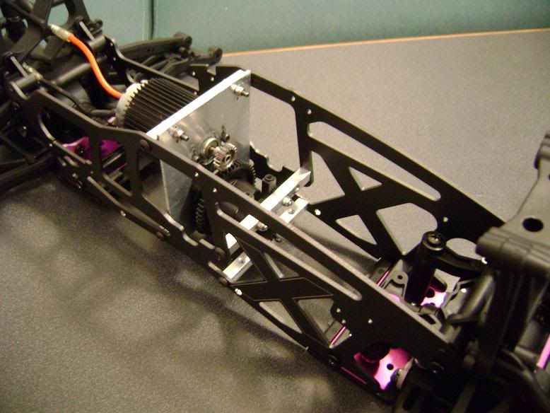 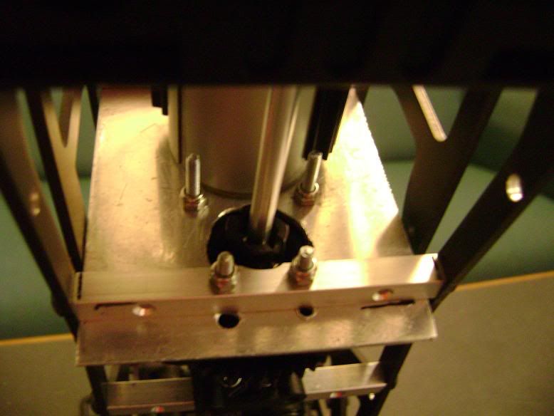 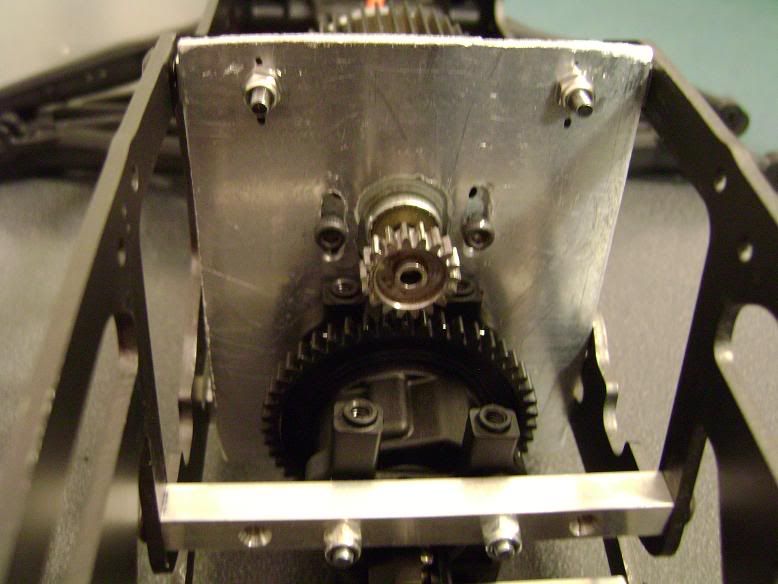 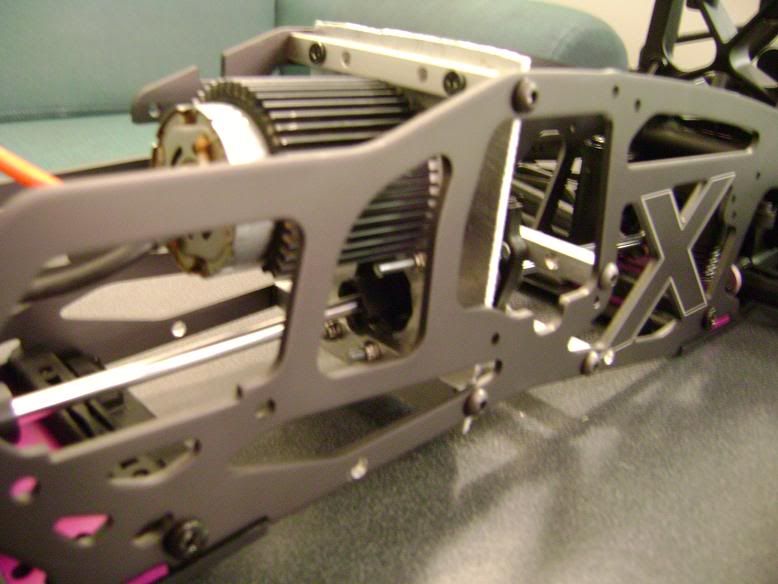
|
|
|
|
|
|
|
|
(#14)
|
|
KillaHurtz
Offline
Posts: 2,958
Join Date: Apr 2006
Location: Bucks Co, PA
|
04.07.2009, 10:41 PM
Yes that gives some good ideas and clarification of what I was thinking about the mounting points. I like how you used that lower chassis mount. I was focused on the tranny mounts, but it looks like yours are more square. Thanks
|
|
|
|
 |
| Tags |
| savage xl mgm 8s |
«
Previous Thread
|
Next Thread
»
| Currently Active Users Viewing This Thread: 1 (0 members and 1 guests) | |
| Thread Tools | |
| Display Modes | Rate This Thread |


 Hybrid Mode
|
|

Powered by vBulletin® Version 3.8.11
Copyright ©2000 - 2026, vBulletin Solutions Inc.
vBulletin Skin developed by: vBStyles.com
Copyright ©2000 - 2026, vBulletin Solutions Inc.
vBulletin Skin developed by: vBStyles.com