


|

|
(#16)
|
|
Check out my huge box!
Offline
Posts: 11,935
Join Date: Aug 2007
Location: Slidell, LA
|
12.09.2010, 11:43 PM
Ok, I am not quite with it today.
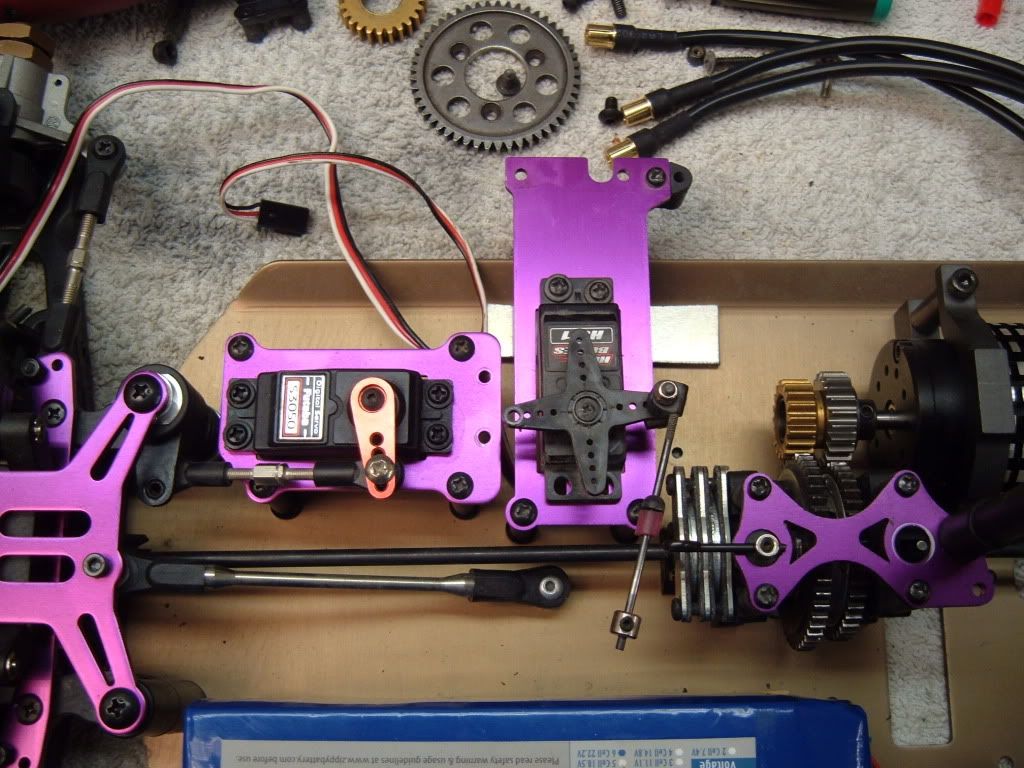
For some reason I thought I could swap the steering bellcranks and put the servo on the other side...WRONG So I got the motor out of the flux, set it up on the same side as the steering servo, and found some small pinions, 18/22, for the 2 speed adapter. It all fits, with room to slide the motor over for the smaller 16/20 gearing I need to order. Also, the brake servo will fit behind the steering servo and in front of the centerfront bulkhead. So good to go. Battery fits a little better on the opposite side, and the MMM looks lost behind it. I do need to figure out some sort of tx/bec mount or box. Only issue is that the rear brace off the rear diff bulk will need to be moved to clear the motor. Looks like I can swap in a longer turnbukle and run it slightly diagonally and mount it on the other side of the rear center driveshaft. Forgot to take pics but will do that in the morning. |
|
|

|
|
|
|
|
(#17)
|
|
|
Soldermaster Extraordinaire
Offline
Posts: 4,529
Join Date: Apr 2007
Location: Plymouth, MA, USA
|
12.09.2010, 11:45 PM
Quote:

|
|
|
|
|

|
|
|
|
(#18)
|
|
|
Check out my huge box!
Offline
Posts: 11,935
Join Date: Aug 2007
Location: Slidell, LA
|
12.10.2010, 12:26 AM
Quote:
|
|
|
|
|
|
|
|
|
(#19)
|
|
Check out my huge box!
Offline
Posts: 11,935
Join Date: Aug 2007
Location: Slidell, LA
|
12.10.2010, 10:45 AM
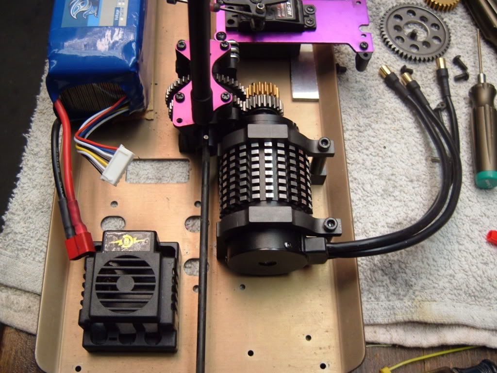
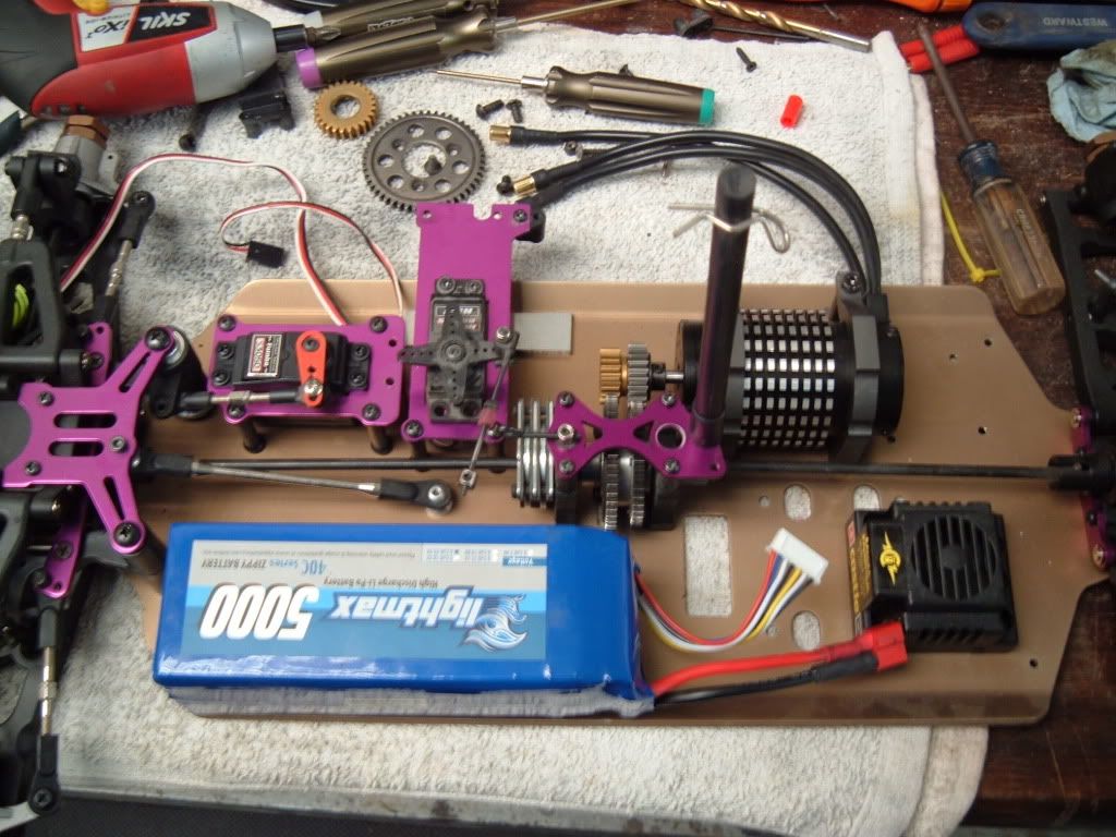
Here are some pics with my current configuration. Think this will be the final one, so I will get to making the motor mount plate.
|
|
|
|
|
|
|
|
(#20)
|
|
Destroyer of Tires
Offline
Posts: 626
Join Date: Feb 2009
|
12.10.2010, 08:43 PM
Instead of using a longer turnbuckle for the rear chassis brace, how about moving it to the outside of the mount. I know the mounting screw won't be double shear then, but it is only for onroad. Although if you have a longer turnbuckle lying around... Looks nice though, never knew Hot Bodies made a 1/7, thanks for sharing.
|
|
|
|
Setup. |
|
|
|
(#21)
|
|
JERRY2KONE SUPERMAXX
Offline
Posts: 3,452
Join Date: Sep 2006
Location: HAYMARKET VIRGINIA
|
Setup. -
12.10.2010, 11:09 PM
Hey James. Your setup looks pretty clean to me and practical to. The only issue I see so far is the battery center diff gear spacing. I will assume that you plan on using a battery tray of some kind to keep them from coming into contact with each other. That could be one ugly incident. Looks good James.
|
|
|
|
|
|
|
|
(#22)
|
|
KillaHurtz
Offline
Posts: 2,958
Join Date: Apr 2006
Location: Bucks Co, PA
|
12.11.2010, 12:31 AM
How radical are you thinking about getting? There seems to be quite a bit of real estate on that chassis. Any thoughts to maybe moving the center diff back a few inches and offset towards the batt side, that flips the motor around too, and you could bring it and the battery closer to the center line of the chassis?
There seems to be some space around the nitro motor mount holes where you could fit the CD in. Makes mounting the rear brace a bit trickier tho. F brace could move to other side of driveline, which is fine as the brake servo goes back w/ the CD, and there may be space in front of the motor. Just a wild thought. GLWTB. |
|
|
|
|
|
|
|
(#23)
|
|||
|
Check out my huge box!
Offline
Posts: 11,935
Join Date: Aug 2007
Location: Slidell, LA
|
12.11.2010, 02:42 AM
Quote:
Quote:
Quote:
Might do this at some point, but sticking to the center drives and stock chassis on this one. I do plan to make the motor plate big enough to go under the center drive and act as a brace. Something similar to the xray truggy chassis brace Mike makes. |
|||
|
|
|
|
|
|
|
(#24)
|
|
Check out my huge box!
Offline
Posts: 11,935
Join Date: Aug 2007
Location: Slidell, LA
|
12.31.2010, 10:01 PM
Ok, little update here. Had some time so I figured out the brake servo mount, and would have cut it to length but the "tires" on my bandsaw have dry rotted, so I had to order new ones.
So I removed the center drive and the other parts and found a nice piece of al, 2/10ths of an inch thick, to use as a combined brace, motor mount etc. Motor will mount to this piece from the underside, as will the brake servo mount and the rear of the battery tray. Will thread holes in it so it can be held to the chassis from the underside thru the stock chassis holes. Plus the front and rear chassis braces will mount thru it, and it will stiffen the center of the chassis, and help keep the gears mesh correctly. The gear mesh will be set with the center drive and the motor mounted to the plate off the vehicle and then the whole assy will be mounted in. I could cut some "windows" in the stock chassis, kinda like a nitro chassis, just depends. Heres a couple of pics, had more but the stupid "smart phone" did not save them correctly...  
|
|
|
|
|
|
|
|
(#25)
|
||
|
RC-Monster Titanium
Offline
Posts: 1,402
Join Date: Aug 2008
Location: Twin Citys Mn
|
12.31.2010, 10:07 PM
im looking forward to seeing how this turns out
Quote:
Quote:
|
||
|
|
|
|
|
|
|
(#26)
|
|
|
Check out my huge box!
Offline
Posts: 11,935
Join Date: Aug 2007
Location: Slidell, LA
|
01.01.2011, 04:31 AM
Quote:
|
|
|
|
|
|
|
|
|
(#27)
|
|
RC-Monster Carbon Fiber
Offline
Posts: 372
Join Date: Dec 2007
|
01.02.2011, 12:10 AM
Due to the length of your project, I would suggest you find a way to fab up a top plate that connects the front and rear of the chassis to cut out flex. I don't think the front and rear braces, in my opinion are not enough to keep the chassis from flexing.
CF Ofna DM-1 Pro CC1717 CF Sportswerks Mayhem ST CF Losi LST2 |
|
|
|
|
|
|
|
(#28)
|
|
RC-Monster Titanium
Offline
Posts: 1,884
Join Date: Jul 2009
|
01.02.2011, 02:47 AM
Kind of like a 1/10 4WD TC right Big House?
Kind of unrelated, but my truggy has a carbon-fiber "spine" so to speak as Big House described, and it has done a great job reducing flex (especially since it's the 6061 RTR chassis, not 7075 Pro). Diggity Designs makes a similar item for the Caster buggy: http://diggitydesigns.com/D3_Caster_EX_UpperDeck.html I spoke to Damon about using setups like this, and he said with the reduced chassis flex you will have to change the suspension setup a little, but overall it will be more consistent. You still need to have a little flex, but shock oil and springs are more predictable than a flexing chassis, and they should be doing the bulk of the suspension "work". And especially with a TC I think a stiffer chassis is the way to go, since the surface is smooth and high traction. |
|
|
|
|
|
|
|
(#29)
|
|
|
Check out my huge box!
Offline
Posts: 11,935
Join Date: Aug 2007
Location: Slidell, LA
|
01.02.2011, 04:37 PM
Quote:
|
|
|
|
|
|
|
|
|
(#30)
|
|
Check out my huge box!
Offline
Posts: 11,935
Join Date: Aug 2007
Location: Slidell, LA
|
01.05.2011, 11:14 PM
Did some work tonight on the center chassis plate. Looks like it will work fine.
Need to order gears from Mike, might as well do that tonight too! Once they come in I can finalize the motor clamps locations and do a few test runs. Also need to make a battery tray, but that covers the construction aspects of this project... |
|
|
|
 |
«
Previous Thread
|
Next Thread
»
| Currently Active Users Viewing This Thread: 1 (0 members and 1 guests) | |
 Linear Mode

|
|

Powered by vBulletin® Version 3.8.11
Copyright ©2000 - 2026, vBulletin Solutions Inc.
vBulletin Skin developed by: vBStyles.com
Copyright ©2000 - 2026, vBulletin Solutions Inc.
vBulletin Skin developed by: vBStyles.com