


|
|

|

|
(#1)
|
|
|
RC-Monster Titanium
Offline
Posts: 1,697
Join Date: Mar 2008
|
06.25.2009, 11:21 PM
Quote:
Hi Brian, The capacitors are low ESR type, Panasonic TS-UP series, 33000uf, 35V. .014 ohms / each at 20khz. We just threw the chokes in there when it seemed we were still getting a lot of voltage ripple from the switching on the ESC. Turns out that the voltage ripple was from ground bounce -- when we measured it differentially, the ripple went away. But, we left the chokes in anyway. :) We are using a Castle Link to drive the controller and to log data -- the ICE can only store about 10 minutes of data at full rate. Richard and Jon cobbled up an application to drive the controller and read data while it is running. President, Principle Engineer Castle Creations |
|
|
|

|

 I picked up an Eagletree 150A logger from a member here so that is taken care of, but the ICE would work just as well.
|
|
|
|
(#2)
|
|
TEAM FUSION
Offline
Posts: 2,041
Join Date: Jul 2006
Location: Iowa... Hawkeye country
|
06.25.2009, 07:32 PM
Very nice PD :)
Losi 8IGHT MM/Neu 1512 1900kv Kyosho 777 T4 MM 5700 B4 LRP XX4 MM 7700 old losi xxcr, MM4600 4s lipo 70mph+ |
|
|
|
|
|
|
|
(#3)
|
|
RC-Monster Mod
Offline
Posts: 6,597
Join Date: Apr 2007
Location: NJ
|
06.25.2009, 09:02 PM
Also looks like setup for high powered brushed mode based on wiring
|
|
|
|
|
|
|
|
(#4)
|
|
Fat Kid Engineering
Offline
Posts: 3,634
Join Date: Jun 2009
Location: Hot as Hell West Central Coast Florida
|
06.25.2009, 09:17 PM
Hey Brian,
To be honest I don't understand everything I've just read but I do savy enough to comprehend that you may need test subjects ? For whatever it's worth, I have several T-RC Packs. They are 2s&3s and all 15C with various mah capacitys. All are like new and willing to sacrifice themselves for the greater good of research . LMK. |
|
|
|
|
|
|
|
(#5)
|
|
RC-Monster Admin
Offline
Posts: 14,609
Join Date: Nov 2005
Location: Des Moines, IA
|
06.25.2009, 10:15 PM
I appreciate that Bondo! I just want to warn everyone that may be interested in donating test subjects that there is a definite possibility that these tests will destroy the packs under test. At the very least, the packs will have a shorter lifespan.
Even so, it's not nearly done yet as I still need the following: - MMM ESC (or any ESC that is capable of brushed mode and at least 200A). - 500,000-1,000,000uF capacitors. Either a bunch of smaller ones paralleled, or one big car audio cap. - Some type of heatsink. Since I'm using so many resistors, maybe just a 1.8" thick piece of aluminum with a couple fans blowing across them. - A container and ventilation system if/when the lipos under test decide to vent/flame. - Assembly involving some pretty heft wire (I have some 8GA and 10GA car audio wire) and a bunch of solder. |
  |
|
|
|
|
|
(#6)
|
|
RC-Monster Admin
Offline
Posts: 14,609
Join Date: Nov 2005
Location: Des Moines, IA
|
06.25.2009, 11:57 PM
Thanks for that info.
For the sake of cost, do you think I'll "need" low-ESR cap(s) if it is ~1F? I already have a 1F cap sitting around, but I'll get some low-ESR ones if I have to. Unfortunately, I don't have the expertise to "cobble" programs of that nature together, so I guess I'll be stuck with the manual method. The best I could probably do is get it to generate the proper signals for the tests, but that's about it. Apps like that aren't my forte. 
|
|
|
|
|
|
|
|
(#7)
|
|
RC-Monster Titanium
Offline
Posts: 1,609
Join Date: Aug 2008
Location: Bozeman, Montana
|
06.26.2009, 12:21 PM
I know you just spent all that money on resistors but did you ever consider a motor mount, motor, and a big prop off a plane?
|
 |
|
|
|
|
|
(#8)
|
|
RC-Monster Admin
Offline
Posts: 14,609
Join Date: Nov 2005
Location: Des Moines, IA
|
06.26.2009, 12:23 PM
I did, but figured resistors were cheaper (and safer for me and the dog or cat
). I have some other projects that I can use the extra resistors for, so it's not a total loss even if this doesn't pan out. But, if anyone needs some 3ohm 50w resistors, I have about 100 I could spare.
|
|
|
|
|
|
|
|
(#9)
|
|
RC-Monster Admin
Offline
Posts: 14,609
Join Date: Nov 2005
Location: Des Moines, IA
|
07.08.2009, 07:49 PM
Update:
I was going to build the throttle control circuit myself, but found the Esky EK2-0939 servo tester that is probably more accurate and less prone to "drifting" with temperature, age, etc, so I ordered it. Coming from China, so it'll be a week or so before it gets here. In the meantime, I noticed it needed a power supply from 6v-9v, and since the ESC might not provide a stable 6v output on the BEC at the high battery loads I'll be testing, I made a regulated 8v power supply. Nothing special, just a small transformer, a couple caps, and a LM7808 regulator. I happened to have all the parts handy so it was effectively free. I also picked up an Eagletree V3 datalogger from another member here. It came with one USB cable, but I needed another cable, so I made one from one of a billion USB cables I have and the speaker connector from a computer motherboard:  Then, since I needed a temperature probe, but didn't want to pay for one, so I scavanged a thermistor from my pile of computer parts and attached a servo connector on the other end. Works well, is accurate, and has a quick response time. I want to bond a small piece of aluminum to it so I can get a better reading and to reduce any stress on the delicate thermistor:  So, progress is slow, but coming along.
|
|
|
|
|
|
|
|
(#10)
|
|
RC-Monster Mod
Offline
Posts: 6,597
Join Date: Apr 2007
Location: NJ
|
07.08.2009, 08:53 PM
nice - do you wear sandles
|
|
|
|
|
|
|
|
(#11)
|
|
|
RC-Monster Admin
Offline
Posts: 14,609
Join Date: Nov 2005
Location: Des Moines, IA
|
07.08.2009, 09:35 PM
Thanks! I'm anxious to get it done too, but finances don't allow it (if they did, I'd just get a real setup).
Quote:

|
|
|
|
|
|
|
|
|
(#12)
|
|
RC-Monster Spudgunner
Offline
Posts: 2,353
Join Date: Apr 2008
Location: South Dakota
|
07.08.2009, 08:58 PM
I'm still really excited about this. Make sure to test the a123 batts! People get pissed when I say lipos are better then a123s due to voltage drop, but I don't have much to back them up.... Can't wait to see the final product Big G!
|
|
|
|
|
|
|
|
(#13)
|
|
RC-Monster Carbon Fiber
Offline
Posts: 126
Join Date: Mar 2009
Location: Ohio
|
07.08.2009, 10:02 PM
HOLY COW....Impressive, and here I even thougt of oing something like this! The whole money thing is hold back though. Except I was gonna program a Microcontroller to do most the stuff, voltage current temps, plus the whole rpm idea.
Figure since I claimed I might try something like this I felt that I should post my idea just incase it may spur some ideas for others. 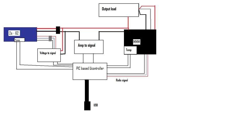 With design it records the main pack voltage with no load, individual cell voltages, pack temp at start, and esc temp at start of test. While testing it would track the main packs total v drop and cell v drop in coralation to different applications (sudden throttle/brake, "cruise" etc) as well as peak and average current draw over a given period of time. All this info will be controlled by a PIC (hopefully most the techy heads know what they are) as well as throttle control will be handled by the pic considering, pics have a servo function with variable pulses and so on, this all will sent via usb to a pc to be debugged on the screen, which I believe theres also a command to "print" the debug values which may be similar to copy paste in which case the values would by plugged into an excel sheet then plotted on a graph. As for the voltage to signal and amp to signal it would basicly by some form of an analog to digital converter that turns voltages/amps to digital pulses sent to the pic and recorded. Futaba 3pk more controller then anyone person needs TC5 top speed drifter 21mph on crappacks and 40 on calc |
|
|
|
|
|
|
|
(#14)
|
|
RC-Monster Admin
Offline
Posts: 14,609
Join Date: Nov 2005
Location: Des Moines, IA
|
07.18.2009, 11:16 PM
A little off-topic, but this sort of drives home the need for a standardized testing and rating.
I was taking some ET graphs of a couple of vehicles and the test results are quite revealing. First up is my CRT.5. Castle ESC, Medusa 36-50-3300, 46/14 running on an Elite 3s 30C 3.3Ah battery. Here is a screenshot of the run:  Next up is my Slash. HobbyWing 80A ESC, Medusa 36-50-2200, 58/11 running on a Maxamps 4s1p 5Ah 20C battery. Here is the screenshot of that run:  All I gotta say is WOW! The Elite held 3.4v/cell at a 149A burst!!! And the average voltage is pretty darn good too! OK, it IS rated for 30C after all, so let's look at the MA pack. The highest burst is 61A, (which is 12.2C by the way) and the voltage fell to 3.12v/cell. Of course this "test" is not repeatable, nor does it show anything conclusive, but there is a definite discrepancy here. |
|
|
|
|
|
|
|
(#15)
|
|
RC-Monster Aluminum
Offline
Posts: 610
Join Date: Feb 2009
Location: Tomball/ Houston Tx.
|
07.19.2009, 03:10 PM
Brian I have a 1F cap and some heatsink material I can donate to the cause. The second pic has 50W resistors on it so it should be perfect size for your setup. Also if you need I can make a fan shroud for it as well.
Jeff |
|
|
|
 |
«
Previous Thread
|
Next Thread
»
| Currently Active Users Viewing This Thread: 1 (0 members and 1 guests) | |

 Hybrid Mode
|
|

Powered by vBulletin® Version 3.8.11
Copyright ©2000 - 2026, vBulletin Solutions Inc.
vBulletin Skin developed by: vBStyles.com
Copyright ©2000 - 2026, vBulletin Solutions Inc.
vBulletin Skin developed by: vBStyles.com