


|

|
(#16)
|
|
Guest
Posts: n/a
|
01.12.2011, 05:23 PM
Another copy
============ Need help Hey, I am becoming worried about the lower plate. To use pretty much any type of motor mount i will have to remove the brace thingy that goes between the upper and lower plates. This is where i become worried. I am scared that on a big jump the CF will brek with the weight of the motor/CD and batteries on it. My plan now is to make a reinforcement plate that sits above the Cf lower plate, this will make the COG a little lower as it will effectively lower the batteries. It should also reinforce, go figure, the lower plate. My question is this, do you think it's needed and if i do make one what type of plate should it be, (Alu or CF / and what design / and what location) I hope this makes sense, my mind thinks it just got mindf**ked NOTE: THIS VIDEO HAS SWEARING, IF YOU DO NOT LIKE IT DON'T WATCH IT http://www.youtube.com/watch?v=lpMmU7AkDvM ========= Well after the loud noise of crickets chirping and the occasional tumbleweed i decided to go ahead and make the Alu plate. It is just a square plate that sits between the CF lower plate and the chassis rails. It lowers the lower plate by 2.5mm (go figure). Anything that will be bolted onto the lower plate will be bolted to both of them. That way i can remove one or the other and the other one will have the holes already in it. also with the batteries i am going to try and mount them to either the upper plate and/or chassis rails while still having them on the sides. I should be able to make a little more progress this week when i get an order in from AMAIN. ========== Had a busy night tonight. But i finally got the driveshafts done. Turns out i don't have to order any custom ones. Revo/Maxx CVD's are the perfect length, if you use two, and fit in the CD perfectly. The only issue is that at the dogbone end, where the bulge is, i had to cut away a lot of material, and i mean alot, these were some THS or something like that CVD's and the centre ones i bought are actually thicker at the dog bone end than the TRX ones so tomorrow i may be putting plastic shafts on my e-maxx sooner than expected. If i had the motor mount i reckon i could be driving this by the end of the week. This motor mount thing is really pi55ing me off. I am actually becoming tempted to use a hyper mount and just mount the servo and esc on the opposite side to the motor to somewhat counter balance it. If i did that though my COG would be at about the top chassis plate, maybe a little higher but not much ============ If anyone is interested the wheelbase is about 1/2 an inch longer than my MBX6T and the width is about 1/2 an inch on either side so i reckon that with half offset LPR's it'll be the same width. However if i put some half offset 40's on it it'll be heaps wider. Also i haven't gotten the towers yet. This build is starting to annoy me. ============ Got some of my goodies today. The body now sits much lower but i don't have to cut it. For the battery boxes; to mount them i will use some button head screws and some lock nuts. To do this i will need to add another plate to the lower plate section. This will mean that the wings are 5mm thick and some parts of the middle will be 7.5mm thick. I'm unsure as to whether i should make it out of alu or CF. it will get scratched to hell as it will be only a little higher than the rear skid. I am thinking i will make it out of alu and just make it so there isn't much material in the middle where it is already 5mm thick. ========== 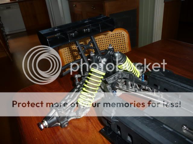  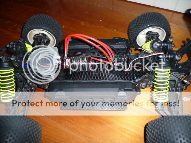
|
|
|

|
|
|
|
|
(#17)
|
|
Guest
Posts: n/a
|
01.12.2011, 05:27 PM
Just to fill in some gaps.
the centre shafts i am using are TRX revo CVD's. The ones that go from the diffs to the wheels. They are the perfect length however they have a little movement in the CV cup. I was originally going to have the motor mounted above the CD by using the RCM universal CD/motor mount. however this was in stock so i used the CD, motor mount and chassis brace out of my Hyper STe Pro. This gives me a very low CG but i am limited to using 1515'ish sized motors. PICS   
|
|
|
|


|
|
|
|
(#19)
|
|
Guest
Posts: n/a
|
01.12.2011, 05:30 PM
In the above pic the screws and lock nuts holding the battery boxes (savage flux battery boxes) are protruding from the lower plate.
     So i ground down what was sticking out and had a little fun in the mean time. |
|
|
|
|
|
|
|
(#20)
|
|
Guest
Posts: n/a
|
01.12.2011, 05:33 PM
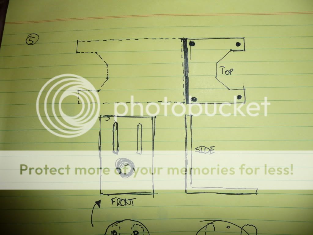
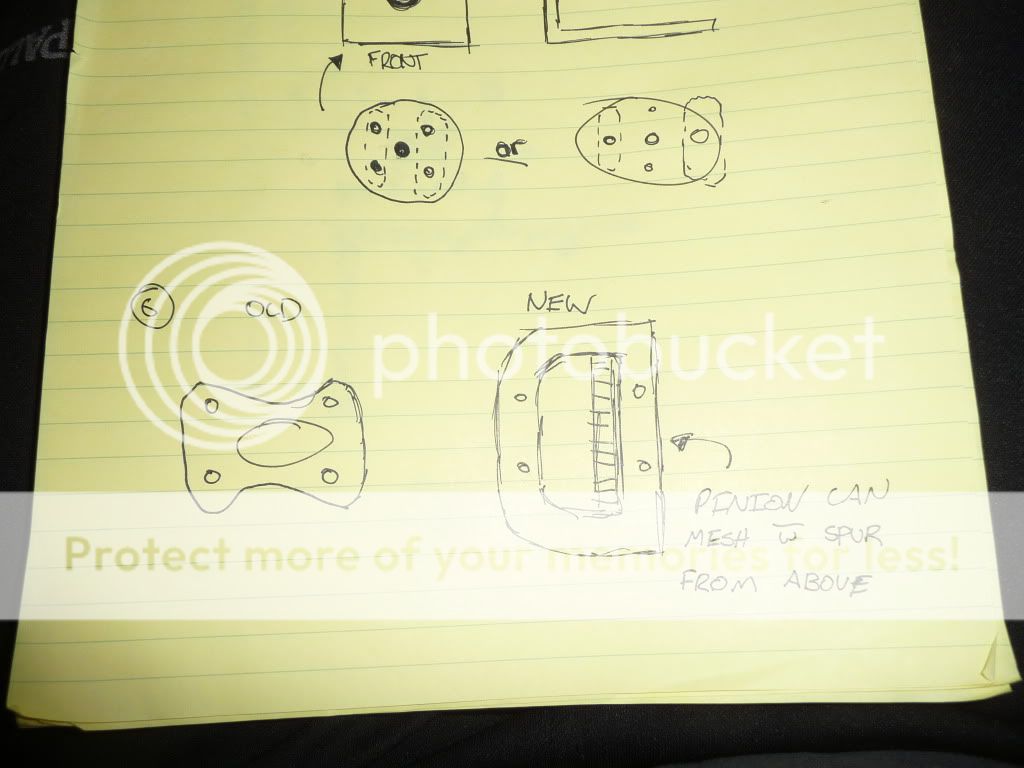
I have now decided to make my own motor mount and it should work well if i can make it properly. If not i will get someone to CNC it for me and it'll be perfect.
Here are the pics, 1) Existing lower Alu plate 2) Existing lower CF Plate 3) Either 2.5mm CF or 1/10" Alu 6061-T6 4) Either 2.5mm CF or 1/10" Alu 6061-T6 5) 6mm 80x80mm Alu angle 6) Either 2.5mm CF or 1/10" Alu 6061-T6  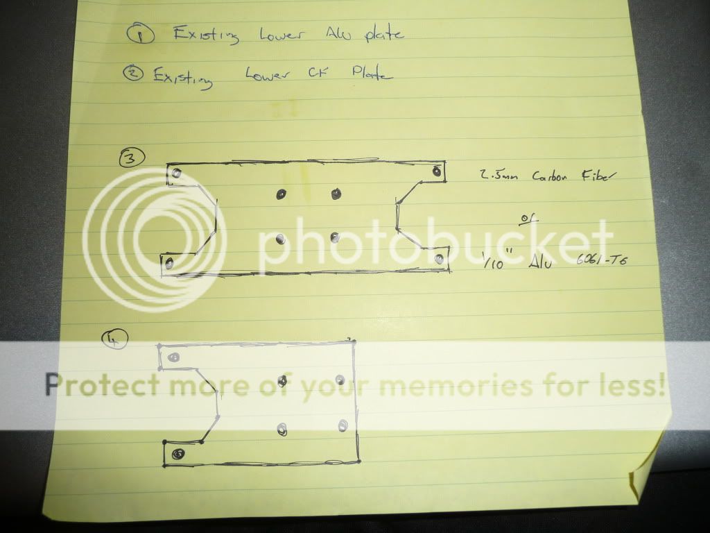 More pics to come. |
|
|
|

|
|
|
|
(#22)
|
|
Guest
Posts: n/a
|
01.12.2011, 05:37 PM
More copies
============ Back to my new setup idea. I have some questions and some more info. 1) i have two options for the motor mount/CD mount. I can either have the motor mount separate to the CD mounts or i can have the motor mount act as the support for the rear of the CD. I am going toward the idea of having the motor mount act as the rear CD support. 2) I am also thinking of adding some extra strength to the motor mount. As the motor will be at least 25mm above the base of the motor mount i am thinking of having two triangles on either side of the motor. This will add some serious support to the motor mount while still allowing the motor to be raised and lowered fully. (i'll post up some pics to show what i mean). My question is; Can aluminium be welded? Does welding things add alot of weight (the weld)? Does anyone in brisbane, preferably someone from PHDR (easier to meet up that way) know how to weld (stupid question) and would you be willing to weld something for me? Also how hard is it to learn how to weld and also how much would a basic welding unit cost? I think that's it for now but i am tired so my memory is not all that flash ATM. ============== Long story short no sleep for ben last night. I was bored so i did some measurements to fin the min and max pinions for my new motor mount. If i run the 1717 i think i am limited to about a 12t pinion and i can go as far as about 30T if i want to. I have downloaded a trial for AutoCAD and it has helped alot. I did most of the measurements by hand but if i had've used AutoCAD from the start it would've been heaps easier. ============ The mount i am planning to make. The angle alu is 80x80 6mm , thanks Snap, the side triangle like supports will be made of 1/10" alu and will be screwed on with M3 screws. The motor in it is the same diameter as the CC 1717 and is at its lowest point. The big flat cylinder is the spur gear and the long thin cylinder is the diff outdrive. As i don't have the proper measurement for it i am using the bearing that is a little bigger than the outdrive.  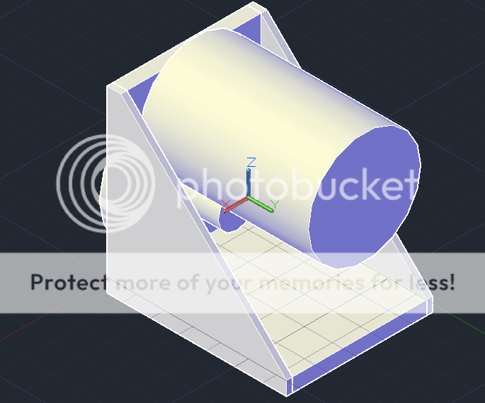   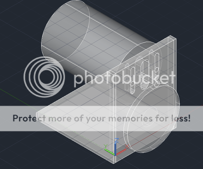 ================= Just thought i might mention this here. LD wanted to sell his XXL and guess what... i bought it. I have some serious plans for this. I have ordered a mamba XL esc and a leopard 4082 1500kv motor. What i plan to do is run this motor or my CC 1520 with the mamba xl with a TDRC mount and with 8s lipo. This is another reason why i'm not doing my e-maxx chassis thing. =============== Well be prepared for another back flip. ...here it is... I have decided to have the motor mount separate to the diff housing/supports. This will make making the motor mount heaps easier and better IMO as pinions will be easier to use (i can explain further if you want). Also in the pictures of the motor mount i have used a 80x80 piece of angle alu but seeing as the CD will need to be in the middle of a 120mm plate i will need to remove some material to make it all fit. the idea will still be the same with the two triangles supporting the motor plate. Also for the rear motor support i will have the support posts mounted on the upper plate. My idea for this is to make 2 support plates. I will be doing one for the 1717 and the other to work with STD 42mm motors. This will mean that rather than the motor support supporting the motor in one little place it'll be supporting it through the whole lower half of the motor. not sure if i have mentioned this before but i will need to make a new upper plate as the current one is a little too weak where the current motor is and it won't look as good with the new setup as the new plate will. I will need to make a new CD upper support plate but this will not be connected to the motor mount as it wont be needed and will add useless weight (i hear some of you saying... what about the triangles...useless weight) but to me they are less useless. Also they should give the motor mount a good look as the two triangles will somewhat shield the motor. ================ Time for another late night/early morning speel. I am thinking about buying a mill as it'll allow me to make higher quality bits and pieces than what i can make currently. I know i will use this but to me it seems like a bit of a waste of money if i am the only one using it. So i have been thinking that maybe if i can make some other mounts for people then my purchase will be more worth it. Another option for me is to make my motor mount out of steel rather than aluminium. There are a few things that i am unsure of about doing this though. 1) steel is far heavier than aluminium 2) steel is cheaper than aluminium 3) Steel unlike aluminium can be welded with something other than a TIG welder. I am thinking that i will buy both a mill and a welder (most likely arc) as it will make me sell off a few kits so that i have enough money to buy both. From what i have read you can buy a mini-mill for about $600 and a ARC welder for about $150. This'll mean that i will need to sell off a few kits so if you are interested in buying one of my kits PM me and i'll tell you if it's available. i probably should've posted this in my blog but CBF'ed ================= That's it for the copies. If you have any questions feel free to ask and i'll try to answer. Thanks, B-M |
|
|
|
|
|
|
|
(#23)
|
|
RC JUNKIE!!!!
Offline
Posts: 191
Join Date: Jul 2010
Location: Schererville,IN
|
01.12.2011, 07:42 PM
Looks really BADA$$!!
|
|
|
|
|
|
|
|
(#24)
|
|
Guest
Posts: n/a
|
01.12.2011, 08:16 PM
Thanks,
It should look alot cleaner when i am finished making the new motor mount. Also i don't think i mentioned this here. When i am done with the new motor mount i will be running a CC 1717 motor and a CC mamba XL esc. |
|
|
|
|
|
|
|
(#25)
|
|
RC JUNKIE!!!!
Offline
Posts: 191
Join Date: Jul 2010
Location: Schererville,IN
|
01.12.2011, 08:41 PM
1717 on 8s will rape!!!!
|
|
|
|
|
|
|
|
(#26)
|
|
Guest
Posts: n/a
|
01.12.2011, 08:45 PM
I won't be running the 1717 on 8s. Not even on 6s. I'll mainly be running it on 4s as i'll be racing this if it performs pretty well.
I may put the MMM XL in my other XXL and run it with a leopard 1500kv or CC 1520 motor on 8s lipo for some fun |
|
|
|
|
|
|
|
(#27)
|
|
RC-Monster Carbon Fiber
Offline
Posts: 280
Join Date: Apr 2008
|
01.13.2011, 08:30 AM
Can I interject young fella?
That 1717 on 4S is very slow. If you run it on 6S it's got a comparable RPM to that of a nitro & RPM means better speed. 1717 = 1580kv x 14.8 = 23384 rpm " " = " " x 22.2 = 35076 rpm I see you're running 2 packs, so, why not run two 2200mAh 6S still light & balanced yet superbly fast. Your choice, I just thought I'd throw you some ideas. Nice setup by the way. A little more complex than mine, but, I only made mine for fun & games. Very cheaply I might add!! Good luck with the build & keep the updates & pics coming. MP7.5 Kanai III Tekno Neu 1515/2.5D 1700kv MM 4S LST 2 Carbon CC 1717 1Y 1580kv MM 6S Futaba 3PKS Spektrum Pro |
|
|
|
|
|
|
|
(#28)
|
|
RC JUNKIE!!!!
Offline
Posts: 191
Join Date: Jul 2010
Location: Schererville,IN
|
01.13.2011, 08:39 AM
Yea what he said about the batteries ^^
|
|
|
|
|
|
|
|
(#29)
|
|
Guest
Posts: n/a
|
01.13.2011, 09:02 AM
I am sticking with 4s as i have heaps of 2s batts so for racing that makes sense for me. Also the track i run on is good for the low 30's in MPH.
Who know i may put the 1717 in my basher XXL and put in a 4082 1500kv or feigao 580l 8T motor in my racer. Or i can run a CC 1518. ATM i am running a Tekin RX8 with a 1700kv motor as that's the longest and widest motor i can fit due to the driveshaft. All the motor and esc combo are theoretical ATM and i'll test them to see whats best. Hope this made sense. |
|
|
|
|
|
|
|
(#30)
|
|
Guest
Posts: n/a
|
01.13.2011, 09:03 AM
Also with the current setup i am running a 11T pinion and that's about perfect.
|
|
|
|
 |
«
Previous Thread
|
Next Thread
»
| Currently Active Users Viewing This Thread: 1 (0 members and 1 guests) | |
 Linear Mode

|
|

Powered by vBulletin® Version 3.8.11
Copyright ©2000 - 2026, vBulletin Solutions Inc.
vBulletin Skin developed by: vBStyles.com
Copyright ©2000 - 2026, vBulletin Solutions Inc.
vBulletin Skin developed by: vBStyles.com