

Building an A123 stick pack in Xs2p Format |

|

|
(#1)
|
|
RC-Monster Mod
Offline
Posts: 5,297
Join Date: Mar 2005
Location: SoCal
|
Building an A123 stick pack in Xs2p Format -
02.22.2007, 12:18 AM
Hey guys,
I finally got around to doing some sort of tutorial on how I built my A123 stick packs (from cells taken from Dewalt 36V packs). This way causes a (IMO) perfect 2p setup, where you can use any number of cells in series (of course limited to the maximum length your vehicle can take). In order to do this, the cells should have the nickel strips (welded on by the factory) cut to the width of the cell (so they don't protrude past the diameter of the cell). Here is my explanation of it: 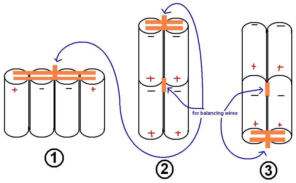 1. Line up 4 cells in a straight line, with the 2 inner ones being either + or -, and the two outer cells having the opposite charge. I used this copper battery braid: http://www.newcreations-rc.com/Produ...umber=HLA99012 It's actually a copper color. Anyways, cut two strips of the copper braid to a length that covers the nickel tabs of all four cells. After doing this, solder the copper braid to the cells in the orientation shown (this way, it doesn't cover up the vents). The orange rectangular lines represent the copper braid, and are pretty representative of its actual width. Also, you can solder a short piece of copper braid to the section between the two middle cells that can be used for adding balancer wires to. 2. Take the two outer cells (of the 4 soldered together) and rotate them 180 degrees, so they sit on top of the (previously) middle cells. When first soldering the two strips in step #1, make sure that there is no solder along the joints where the outer cells are bent at (otherwise, you won't be able to bend the copper braid). After that, make two strips that cover the (now) top two cells. For a 2s2p setup, you will solder the main power wires on these. You can also solder on a short piece of copper braid for balancer wires. 3. Tilt the pack so that you can see the terminals of the bottom two cells (shown in "3D"). Do the same thing with the two copper strips as in #2, along with the short piece for a balancer wire connection. This end will also have a power wire connected to it. Notes: -In step #1, I like to use strapping tape to tape the two middle cells together before soldering them to keep them from moving around (and potentially messing up the soldering). Since these cells won't be separated during the rest of the building process (or ever, for that matter), this tape can be considered permanent. -In step #2, you can lay the pack on a flat surface and tape the two top cells together before soldering the top terminals. You can also use the strapping tape along the length of the pack to keep the pack from flexing between the two groups of cells. -For a 3s2p pack, you would do the same process, except that in step #2 you would add two outer cells to the top two cells like in step #1, and then finish off steps #2 and #3. You could repeat this to make a Xs2p format (where x is any number of cells in series). When finished, you can top the pack off with some shrinkwrap. The shrinkwrap needs to have a minimum (flat) width of 70mm to fit this stick pack. Let me know if any of it doesn't make sense, and I'll do my best to explain. BTW, I have done a total of 4 of these, with two 2s2p and two 3s2p, where a 2s2p and 3s2p are used as 5s2p in my Revo and X-Terminator. For quite a few runs now, these packs have held up very well! |
|
|

|
|
|
|
|
(#2)
|
|
RC-Monster Admin
Offline
Posts: 14,609
Join Date: Nov 2005
Location: Des Moines, IA
|
02.22.2007, 01:05 AM
Nice write up MM!
How do you keep the solder from wicking along the braid so you keep a bendable area clear of solder? You must be using a fairly hot/hi power iron so the actual soldering is fairly quick (~5 sec max). To make a stacked 3s2p pack (for a total of a 6s2p pack), it sounds like it would be fairly easy to make two 3s2p packs and then simply connect them using a braid at the end. Do you have pics of the actual process? It might help people visualize a little easier with the actual parts used... |
  |
|
|
|
|
|
(#3)
|
|
RC-Monster Mod
Offline
Posts: 5,297
Join Date: Mar 2005
Location: SoCal
|
02.22.2007, 01:11 AM
To keep solder from wicking along the braid, I just used an amount of solder that didn't allow it to travel too far. My iron is pretty hot (I set it ~750-800 deg.), but I hold it for more than 5 secs. sometimes.
I never did get any pics of the process, unfortunately. The first time I wasn't sure if it would work (didn't know if it would be worth it to document the process), and the second time I was under time pressure so I couldn't get pics/do a writeup. If anyone wants me to build a pack for them, I'd be glad to document the process at the same time :). |
|
|
|
|
|
|
|
(#4)
|
|
RC-Monster Admin
Offline
Posts: 14,609
Join Date: Nov 2005
Location: Des Moines, IA
|
02.22.2007, 01:16 AM
Well, if you're offering; sure, build me a 6s2p pack.
. . . Ooooohhh, you want me to pay for them? ;) :005: As far as the wicking goes, I've used those little locking needle-nose pliers to clamp the braid where I wanted the solder to stop. Seemed to work well, but I was working with braid that was quite small. I wonder if that trick would work here as well. |
|
|
|
|
|
|
|
(#5)
|
|
RC-Monster Admin
Offline
Posts: 10,480
Join Date: Feb 2005
|
02.22.2007, 02:55 AM
Great work Metal!
You guys know any companies that sell these dewalt packs for cheap? |
|
|
|
|
|
|
|
(#6)
|
|
RC-Monster Mod
Offline
Posts: 5,297
Join Date: Mar 2005
Location: SoCal
|
02.22.2007, 03:43 AM
Ebay is the best bet for U.S. customers (~$100 + shipping per pack), but for outside the U.S., you might end up paying ~$20 a cell (loose cells or Dewalt packs).
|
|
|
|
|
|
|
|
(#7)
|
|
Never Fast Enough
Offline
Posts: 914
Join Date: Jul 2005
Location: UT
|
11.09.2007, 08:34 PM
So, I've made my first 2s2p a123 pack thanks to this excellent thread!
I now need to make a 3s2p pack, now that I've received the cell from the esteemed jonrobholmes that replaces the one I blew up because I'm an idiot.  Anyway, I could easily make one in the style shown above, but I'd like to make it in a pyramid format as crudely depicted in my picture below. The numbers indicate where the cells need to be connected. So, is this about right? Is there a better way to do it? This just seems like it's going to end up really sloppy to me. Any ideas? Thanks! Brian 
|
|
|
|
|
|
|
|
(#8)
|
|
Guest
Posts: n/a
|
11.09.2007, 10:40 PM
A lot of crawler guys are already running "pyramid" shaped 3s1p packs, what I gather is that you'd be putting two of those together end to end?
|
|
|
|
|
|
|
|
(#9)
|
|
Never Fast Enough
Offline
Posts: 914
Join Date: Jul 2005
Location: UT
|
11.10.2007, 12:27 AM
Something like that. The parallel wiring and cell organization is the weird part for me.
It looks like to connect 1 to 1 and 3 to 3, I'll have to run long wires through the pack and tuck them in or something. I also don't want to do this and then have a big spark because I oriented a cell the wrong way. 
|
|
|
|
|
|
|
|
(#10)
|
|
Never Fast Enough
Offline
Posts: 914
Join Date: Jul 2005
Location: UT
|
11.10.2007, 03:14 PM
Ok, so I just built the 3s2p pack like in my picture in the previous post. It didn't turn out nearly as bad as I had envisioned.
It appears to be charging well so far. Now I just need to find some good black shrink wrap to hide everything, and I'll be good to go! |
|
|
|
|
|
|
|
(#11)
|
|
RC-Monster Admin
Offline
Posts: 10,480
Join Date: Feb 2005
|
11.10.2007, 03:22 PM
you can get the shrink from maxamps.!
|
|
|
|
|
|
|
|
(#12)
|
|
RC Monster Fiberglass
Offline
Posts: 117
Join Date: Jun 2007
Location: Germany
|
11.10.2007, 03:47 PM
So, this copper braid you were using is basically a de-soldering braid? I never knew you could use them for soldering :D
 Tesla 4 president!
|
|
|
|
|
|
|
|
(#13)
|
|
Never Fast Enough
Offline
Posts: 914
Join Date: Jul 2005
Location: UT
|
11.10.2007, 04:44 PM
I used the same de-soldering braid as what MetalMan used. It worked like a charm. I never thought to use it either before reading this thread.
Well, both my new packs charged well and ran strong. I ordered the shrink wrap from MaxAmps, along with some new red/black 12g noodle wire. The coolest part about having done this the first time is that it will be 10 times easier, quicker, and cleaner the second time. Very cool. |
|
|
|
|
|
|
|
(#14)
|
|
RC-Monster Mod
Offline
Posts: 5,297
Join Date: Mar 2005
Location: SoCal
|
11.11.2007, 12:25 AM
Yeah, this copper braid stuff works AWESOME for building packs like these. I've got a total of three packs, and 28 cells utilized using this soldering method. Everything has held up perfectly so far, and all of the packs are working as good as when I first built them, despite the fact that I applied a lot of heat to the cells.
|
|
|
|
 |
«
Previous Thread
|
Next Thread
»
| Currently Active Users Viewing This Thread: 1 (0 members and 1 guests) | |
 Linear Mode

|
|

Powered by vBulletin® Version 3.8.11
Copyright ©2000 - 2026, vBulletin Solutions Inc.
vBulletin Skin developed by: vBStyles.com
Copyright ©2000 - 2026, vBulletin Solutions Inc.
vBulletin Skin developed by: vBStyles.com