


|

|
(#46)
|
|
RC-Monster Aluminum
Offline
Posts: 764
Join Date: Apr 2008
Location: canada, quebec
|
09.22.2008, 09:25 PM
clean job,,!!!!!im always surprized when i see a mmmv2 (working unit
 ) )and aluminium is pretty hard to tap a small screw size 
|
|
|

|
|
|
|
|
(#47)
|
|
Im not dark, Im over ripened! xD
Offline
Posts: 5,607
Join Date: Sep 2007
Location: Westampton NJ
|
09.22.2008, 09:34 PM
hey mike, i just got a second MMM, running great so far
though i would hear the fan rubbing the case at times R/c Monster Team Driver Jq the car, LST, Sportweks turmoil pro Unconventional Techniques, Superior Results |
    |
|
|
|
|
|
(#48)
|
|||
|
RC-Monster Titanium
Offline
Posts: 1,402
Join Date: Aug 2008
Location: Twin Citys Mn
|
09.22.2008, 09:46 PM
Quote:
Quote:
Quote:
|
|||
|
|
|

 (just kidding Patrick!)

|
|
|
|
(#49)
|
|
RC-Monster Aluminum
Offline
Posts: 764
Join Date: Apr 2008
Location: canada, quebec
|
09.22.2008, 09:48 PM
brushlessboy16....lucky you are ...
me my second v2 failed after 30min.... friday....(i ship today to cc)i have one unit that my friend david lamontagne sold to me...(he run it about 2 hour so far) friday....(i ship today to cc)i have one unit that my friend david lamontagne sold to me...(he run it about 2 hour so far)lets see what happen this wek with this unit.... 
|
|
|
|
|
|
|
|
(#50)
|
|
|
RC-Monster Stock
Offline
Posts: 30
Join Date: Jun 2008
|
09.22.2008, 10:17 PM
Quote:
|
|
|
|
|
|
|
|
|
(#51)
|
|
|
Guest
Posts: n/a
|
09.23.2008, 12:21 AM
Quote:
I modded my case before I powered up my V2, I removed some material from the bottom of the case to make room for the fan connector and I also did a small amount of relief work for the induction coil. Regardless the BEC failed just after calibration with my radio. I beleive the case is a problem and is possibly causing a few malfunctions but believe a more likely explanation would be A: Faulty parts B: Assembly fault (my money is on this) I would think that after all the V1 failures that the CC techs would of gone over the design of the BEC with a fine toothed comb. This leads me to believe that the same problem from the V1's is also effecting the V2's. Is it possible an assembly technique is to blame here? Has anyone noticed how close the control board is to the back of the FET board? I wonder if when they solder these boards together there is some sort of issue??? Just some observations... I love CC  regardless regardlessWhat are everyone else's theories???? |
|
|
|
|
|
|
|
|
(#52)
|
|
|
RC-Monster Titanium
Offline
Posts: 1,777
Join Date: Feb 2008
Location: Illinois
|
09.23.2008, 12:31 AM
Quote:
|
|
|
|
|
|
|
|
|
(#53)
|
|
|
RC-Monster Carbon Fiber
Offline
Posts: 220
Join Date: Feb 2008
|
09.23.2008, 11:32 AM
Quote:
|
|
|
|
|
|
|
|
|
(#54)
|
|
RC-Monster Mod
Offline
Posts: 6,597
Join Date: Apr 2007
Location: NJ
|
09.23.2008, 01:41 PM
2nd the issue with the heatsink - I think CC should go back to soldered wires. The cups are way to close - I would say touching the heatsink.
The only thing that I believe is stopping a short is the laquerer that is put on - however when cleaning the esc with buggy blast and a compressor most of the laquerer came off so VERY worried about picking up a short. Personally leads are fine by me.... |
|
|
|
|
|
|
|
(#55)
|
|
|
RC-Monster Carbon Fiber
Offline
Posts: 220
Join Date: Feb 2008
|
09.23.2008, 01:50 PM
Quote:
|
|
|
|
|
|
|
|
|
(#56)
|
|
RC-Monster Mod
Offline
Posts: 6,597
Join Date: Apr 2007
Location: NJ
|
09.23.2008, 02:23 PM
Not sure I could get tape or shrink down the back...
|
|
|
|
|
|
|
|
(#57)
|
|
RC-Monster Carbon FIBRE NOT FIBER!
Offline
Posts: 701
Join Date: Apr 2008
Location: Brisbane, Australia
|
09.23.2008, 06:58 PM
weird, mine are spaced out far enough to get at least tape perhaps a bit of heat shrink. I hadn't thought of this at all actually. thanks for bringing it up!!!
edit: u know, both the fins near my battery terminals are bent! this means they are touching/have touched.... also at the bottom i think the esc IS attached to them... im sure they would have thought about this a little???? perhaps its impossible to short for some random reason..? Monster Max Still Working... JR SX3 Neu 1512 2D/S 12t pinion 4800 zippy-r XRAY xt8 MMM Neu 1512 3D/F 11t pinion 6s 5000 Flightmax/ 4s 4000 Turningy |
|
|
|
|
|
|
|
(#58)
|
|
|
RC-Monster Carbon Fiber
Offline
Posts: 220
Join Date: Feb 2008
|
09.23.2008, 08:45 PM
Quote:

|
|
|
|
|
|
|
|
|
(#59)
|
|
RC-Monster Brushless
Offline
Posts: 2,085
Join Date: Sep 2007
|
09.23.2008, 09:34 PM
I've been following this thread. Very interesting points you guys are discovering. Jhautz also showed in detail about the possible fan plug issue.
I opened mine back up to check out the heat sink you guys have been discussing. I felt it was worth pictures. Here they are: In this first picture, please notice that my motor power cups have ample spacing. 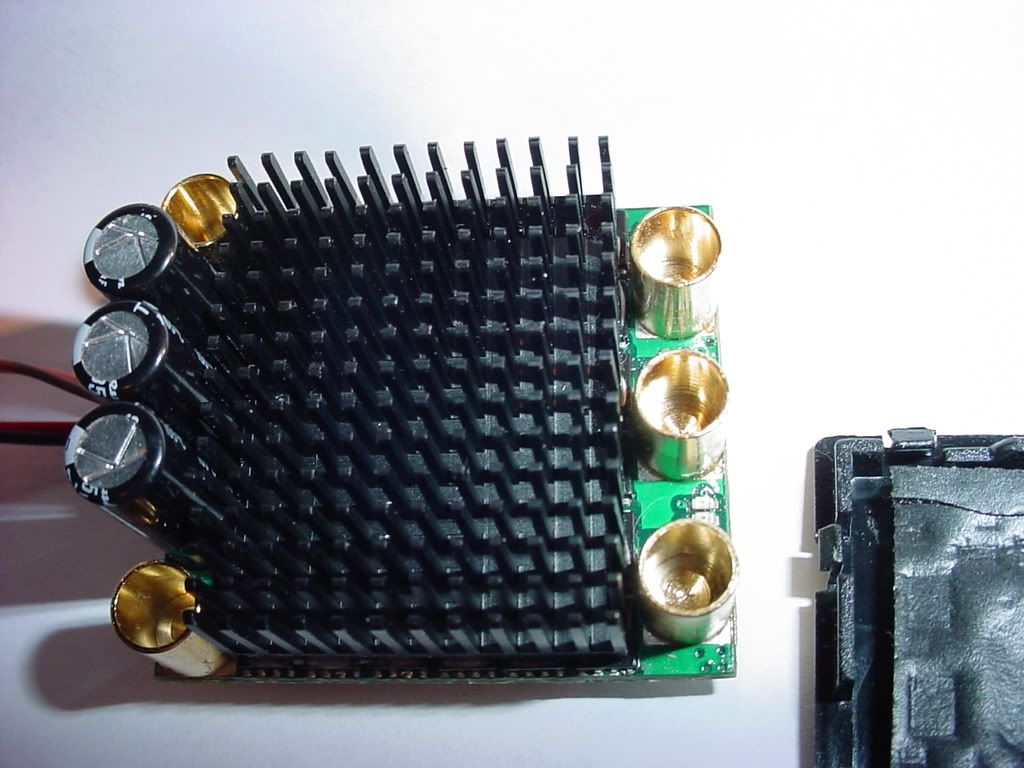 In this picture, my power lead cups are touching the heat sink. Bent heat sink pins as previously mentioned. 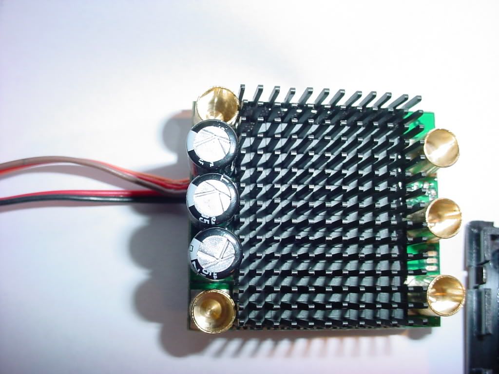 This last picture shows the lower case mod that I did to create clearance for the fan plug. IMO, it's not necessary to go completely through the plate. 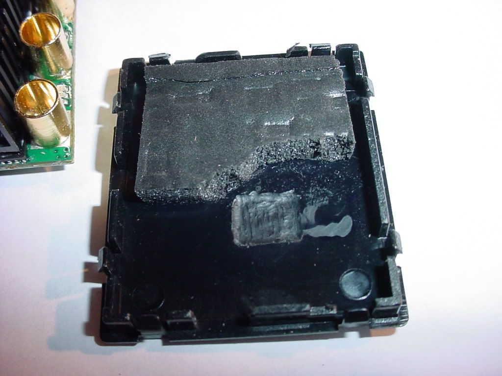 Please Note: In the upper right hand corner of this last picture, I found a resistor riding right on the support rail. I also removed material to clearance for that. What can I do about the power lead cups touching the heat sink? I don't have a good feeling about this. Those pins will flex/rub under shock and vibration I'm sure. IMO, this should have additional clearance to prevent problems. |
|
|
|
|
|
|
|
(#60)
|
|
|
RC-Monster Admin
Offline
Posts: 14,609
Join Date: Nov 2005
Location: Des Moines, IA
|
09.23.2008, 09:49 PM
Quote:
|
|
|
|
|
 |
«
Previous Thread
|
Next Thread
»
| Currently Active Users Viewing This Thread: 1 (0 members and 1 guests) | |
 Linear Mode

|
|

Powered by vBulletin® Version 3.8.11
Copyright ©2000 - 2026, vBulletin Solutions Inc.
vBulletin Skin developed by: vBStyles.com
Copyright ©2000 - 2026, vBulletin Solutions Inc.
vBulletin Skin developed by: vBStyles.com