

Thoughts on Controller Longevity Design |

|

|
(#1)
|
|
RC-Monster Brushless
Offline
Posts: 2,085
Join Date: Sep 2007
|
Thoughts on Controller Longevity Design -
09.11.2009, 01:08 AM
Today at work, I dissected an overheating Brushless Controller for one of our larger double pallet jacks. This uses a 24 volt Lead acid battery. (750 amp hour)
This controller is rated for 24 to 36 volt duty and has a 400 amp capacity. We were doing amp draw tests, since the leads were fried going to the motor. In fact, everything was getting hot and something was thermaling, causing it to shut down. Using an Amp Clamp with the drive tire off the ground, amp draw would spike to the 70 range on acceleration, then taper off to about 36 amps at top speed. The motor in use is a brushless AC induction motor rated at 3.3kw. I brought two of the cards home from the controller, since we replaced this one with a new unit. I did not bring the main brain board. The Power card (FET Board), and another board that houses 22 - 1200uf low esr caps rated for 50 volts. This board also has current detecting hardware. We felt like 36 amps was alot to be running at no load. (864 watts) The Drive Tire needed replaced anyway, so the forklift Tech I was working with decided we should do a test under a load. He let the jack down, placed the drive tire on the floor, got up against something solid and opened up the throttle. Didn't take long before we could smell what was left of the drive tire getting hot and starting to smoke, but the interesting part was.......... This controller limits the amp draw to 400 amps. Amp drawn spiked up to 350 amps, then rose on up to about 395 amps and stayed there for the duration of the test. My Question is: Is it the cost factor and complexity of the Hardware and Firmware the prohibits using this type of setup in our Brushless ESC'S? This would add to the longevity a GREAT deal and cure alot of other problems as well. Give me some thoughts guys. I hope Castle responds to this. But in the meantime, check out these boards. Notice the two round components on the first board? Current Detection. 2 of the Motor Leads come up through these, the 3rd Motor lead has nothing.  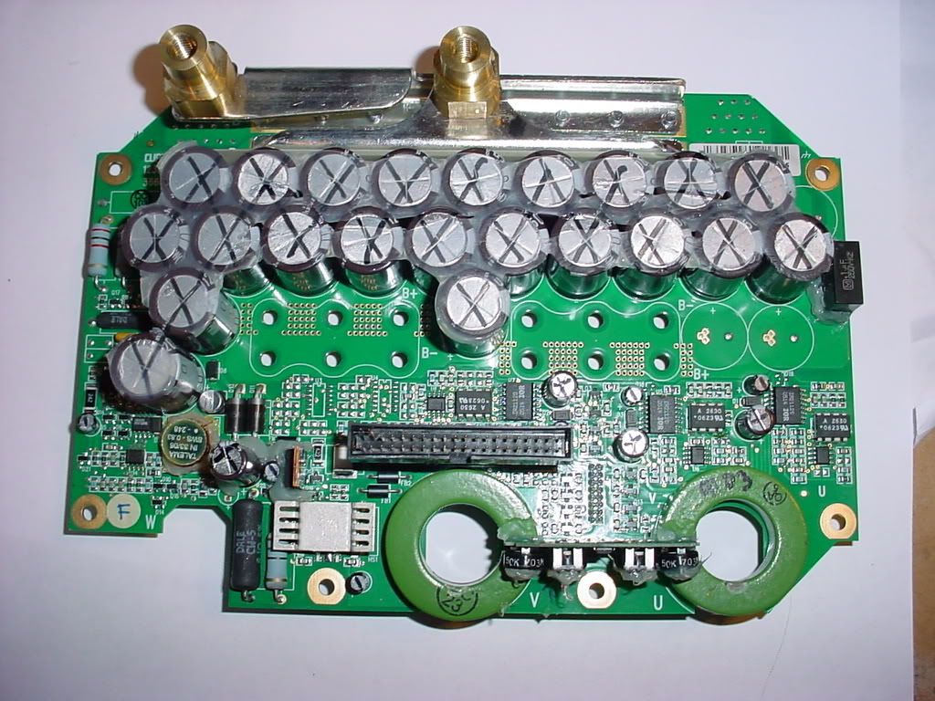 Here's the FET Board. Remember, 24 to 36 volt operating range at 400amps. This setup does use regenerative braking. 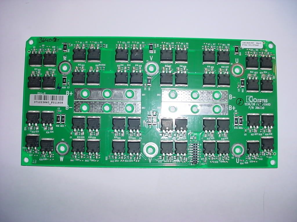
|
|
|

|
|
|
|
|
(#2)
|
|
i pwn nitro
Offline
Posts: 769
Join Date: Nov 2008
Location: with ur GF
|
09.11.2009, 08:15 AM
pretty impressive rig!!
that's what i need for my nissan van to make it BL 
the porthole from the noob world an here has been opened!! that's how i got in. |
 |
|
|
|
|
|
(#3)
|
|
RC-Monster Titanium
Offline
Posts: 1,697
Join Date: Mar 2008
|
09.11.2009, 09:59 AM
I guess your question is: How do we make a more reliable controller, and what's the costs and tradeoffs involved?
Well, to start with let's talk about the motor. The motor your pallet jack uses is likely a fairly high resistance motor compared to the motors used for RC. Industrial motors are designed for continuous duty at low power density. The controller can rely on the fact that the DC resistance of the motor will limit currents to a survivable level for the MOSFETs. Let me go into a little more detail. The current sensors on the board shows are hall effect sensors, which have a fairly low bandwidth (around 50khz or so) -- so it takes the controller somewhere around 20 microseconds for them to respond to an overload condition. The motor that is being driven probably has a resistance of around 40 milliohms, when you include the wiring harness it may be even higher. The resistance of the motor itself would limit currents to under 800 amps or so. This is low enough that the low bandwidth of the current detection would allow time for the current detection to kick in before the silicon in the MOSFETs got so hot that they were damaged. Now, on the RC side, we typically want very high intermittent power for short bursts with lightweight motors. The motors we use, consequently, are VERY low resistance and extremely high power density (the Mamba Monster motor is .007 ohms, or 7 milliohms typical.) At 24V, under stall, the Mamba Monster motor would draw around 3500 amps. At that current level, the controller would destroy itself in around 2 microseconds -- so the controller would already be dead by the time the current sense system would be able to respond to the over current condition. We use a different scheme to determine over current conditions which is faster than hall sensors, but still isn't fast enough to catch every over current condition before damage occurs. The reason is the power density of the controller means that inherently, the controller is much more "on edge" than an industrial controller: We want controllers that are small and light - - the industrial controller shown is probably, what, about 4 x 6 inches in size? That's 24 square inches of circuit board. It's also attached to a large heat sink (not shown.) So, that that industrial controller has a power density of about 400 watts per square inch. The Mamba Monster has a power density of about 1800 watts per square inch. Our newest controller, the Phoenix-ICE-HV-160 has a power density of about 3200 watts per square inch. These power densities mean that the hobby controllers are under considerably higher stress than their industrial cousins. We also build industrial controllers and military controllers. But they are not controllers with power densities that even come close to the power densities of our hobby controllers. It's possible to build more reliable controllers for hobby, but there would need to be sacrifices in performance -- higher resistance motors (lower power output, lower power density) significantly larger, heavier controllers with much higher price tags. President, Principle Engineer Castle Creations |
|
|
|
|
|
|
|
(#4)
|
|
working on a brushless for my wheelchair.....
Offline
Posts: 4,890
Join Date: Mar 2007
Location: minnesnowta
|
09.11.2009, 10:39 AM
Patrick- I love your write ups, I learn so much from you.
Any chance you could share some knowledge in this thread http://rc-monster.com/forum/showthread.php?t=23401 here on RCM about motor pole count and how it affects performance? No biggie if you can't (we already appreciate what you do here) but you don't know unless you ask. Thanks for reading. -Harold Baumann It's "Dr. _paralyzed_" actually. Not like with a PhD, but Doctor like in Dr. Pepper. |
|
|
|
|
|
|
|
(#5)
|
|
RC-Monster Brushless
Offline
Posts: 2,085
Join Date: Sep 2007
|
09.11.2009, 12:44 PM
[QUOTE=Pdelcast;319966]
We want controllers that are small and light - - the industrial controller shown is probably, what, about 4 x 6 inches in size? That's 24 square inches of circuit board. It's also attached to a large heat sink (not shown.) So, that that industrial controller has a power density of about 400 watts per square inch. The Mamba Monster has a power density of about 1800 watts per square inch. Our newest controller, the Phoenix-ICE-HV-160 has a power density of about 3200 watts per square inch. These power densities mean that the hobby controllers are under considerably higher stress than their industrial cousins. QUOTE] The Boards shown in the pictures are 4" X 8" by themselves. By the time you include the casing and yes, the Large Heatsink attached to the rear, the complete controller grows to a size around 8" X 12", being around 6" thick. We are headed toward this type of technology being included in our daily drives to and from work. I WAS very excited about the announcement of GM's production of the Chevy Volt until I recently read they changed the setup. In the beginning, the IC Engine/Generator was to kick on after the Battery was depleted to supply the drive motor AND recharge the Battery. After doing so, it would turn off, until the Battery was depleted again. Somewhere between initial announcements and production, this scheme changed. Now, the ONLY Battery travel is the first 40 miles. Then the IC Engine MUST run fulltime, until YOU recharge at home. There is a sizing problem in this configuration. Battery Technology is growing by leaps and bounds along with motor/controller Technology. This first attempt by GM will be a flop unless they change the setup again not to mention they are already 10K outside of their target price. A Better configuration, I believe, will be one that uses multipole brushless hub motors. 32 poles or more, that are housed inside what we know now to be the brake drum. No Drivetrain. Direct 4 wheel drive. Independant Traction Control with a Computer over seeing everything. I want to further my Education in this field. I knew if there was a person that could answer my questions about this Industrial setup, it would be you Patrick. I learn very much from your Posts. Thank you for taking the time to share your insight with us. |
|
|
|
|
|
|
|
(#6)
|
||
|
RC-Monster Titanium
Offline
Posts: 1,402
Join Date: Aug 2008
Location: Twin Citys Mn
|
09.11.2009, 08:02 PM
so i want to add my dumb question to this
could we use the mmm to power a motor that size under a simalar load or would the mmm burn up? we are starting a brushless go-cart project this winter Quote:
Quote:
|
||
|
|
|

|
|
|
|
(#7)
|
|
i pwn nitro
Offline
Posts: 769
Join Date: Nov 2008
Location: with ur GF
|
09.11.2009, 09:59 PM
this must be a completely different principle but still...
the cruddy traxxas VXL speed controller has a stall protector doovit... so when i gave rock crawling a bash with the rustler and the motor was on the brink of stalling or below a certain RPM threshhold the ESC cut power to the main board and would not give it back until the throttle deadband was re-set. could this principle be manipulated to work when the motor is reving it's nuts off under load? shaun the porthole from the noob world an here has been opened!! that's how i got in. |
|
|
|
 |
«
Previous Thread
|
Next Thread
»
| Currently Active Users Viewing This Thread: 1 (0 members and 1 guests) | |
 Linear Mode

|
|

Powered by vBulletin® Version 3.8.11
Copyright ©2000 - 2026, vBulletin Solutions Inc.
vBulletin Skin developed by: vBStyles.com
Copyright ©2000 - 2026, vBulletin Solutions Inc.
vBulletin Skin developed by: vBStyles.com