

Finally got me an Eagletree Data Logger! |

|

|
(#1)
|
|
RC-Monster Brushless
Offline
Posts: 2,085
Join Date: Sep 2007
|
Finally got me an Eagletree Data Logger! -
12.26.2009, 10:43 PM
Well I finally got me an Eagletree Data Logger!
 I made a run with my E Revo with Medusa Setup and my V2 Monster finally bit the dust!  So it was time to change the entire setup around. This setup is one of the old HV4400 Maxx sensored Motors upgraded with the Sintered Rotor w/5mm shaft. I have no idea what top speed this is geared for. LOL It is geared 14/52 using Mod 1 gears. ESC of choice is the MM Pro! It does have some power handling ability Power Supply is a pair of Turnigy 4S 20C 4000mah wired parallel. Just a few short bursts on the graph. It's dark here, but I'll get some good graphs tomorrow. Ever seen a 4S setup hold 3.91 volts per cell under a 108 amp Load? There is MUCH experimenting to be done! Check this out! 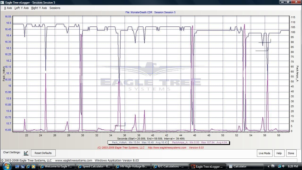
|
|
|

|
|
|
|
|
(#2)
|
|
RC-Monster Dual Brushless
Offline
Posts: 4,236
Join Date: Dec 2007
Location: Cape Cod, Mass.
|
12.26.2009, 10:49 PM
pretty cool...keep the updates coming. I am thinking of getting a data logger in the spring, so I will be watching your results closely
2. MBX-5T 1520, MMM ON 5S 3. MBX-5 ONROAD CONVERSION 1515, MMM ON 5S 4. MRX-3 ON ROAD CONVERSION 1512, MMM ON 6S 5. TEN T 2650 T8, MMP ON 3S |
|
|
|
|
|
|
|
(#3)
|
|
RC-Monster Titanium
Offline
Posts: 1,884
Join Date: Jul 2009
|
12.27.2009, 03:30 AM
Looks like the Turnigy cells hold up well under load. I'd like to see the numbers a bit later in the run as well.
An EagleTree is next on my gadget list too. |
|
|
|
|
|
|
|
(#4)
|
|
RC-Monster Aluminum
Offline
Posts: 702
Join Date: Feb 2005
Location: n.c.
|
12.27.2009, 11:10 AM
I have been playing with mine and love it. The turnigy lipo's hold a load well.
phil Slash 4x4 163mph drc rail 150 mph phildogg6@yahoo.com https://www.youtube.com/channel/UC1g...MR6SqQkehkevwA my youtube channel |
  |
|
|
|
|
|
(#5)
|
|
RC-Monster Brushless
Offline
Posts: 2,085
Join Date: Sep 2007
|
12.27.2009, 12:30 PM
Ok, here's a better run. Same Setup.
The two 4S packs of 4000mah Turnigy is what I want to use with a 8S HV setup. When I can locate a HV ESC that is. I think they would do well.  
|
|
|
|
|
|
|
|
(#6)
|
|
RC-Monster Brushless
Offline
Posts: 2,085
Join Date: Sep 2007
|
12.27.2009, 02:09 PM
Just logged another short run on 4S 30C 5000mah Turnigy Packs.
Looks like they hold 3.635 volts under a 109 amp load. This is going to be interesting to compare how different packs hold voltage under a load. I have alot of different packs to put through the testing. Having fun here. Feel free to comment. 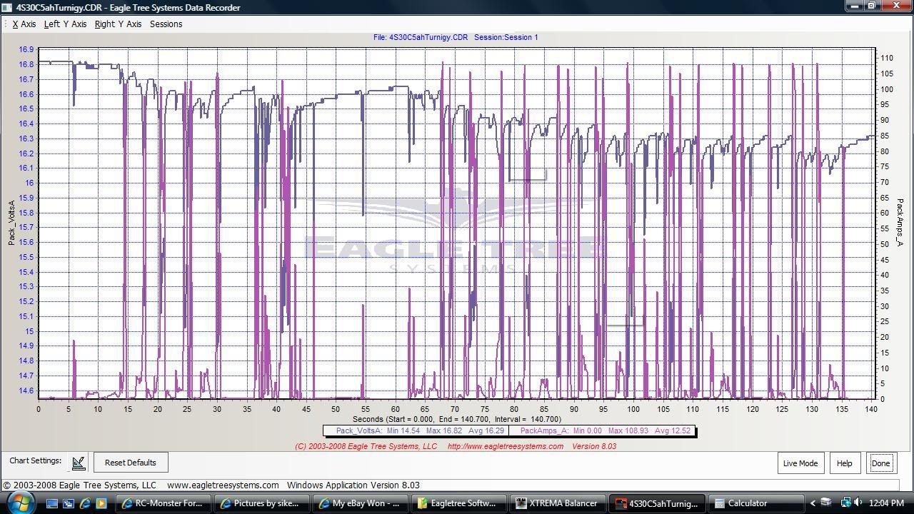
|
|
|
|
|
|
|
|
(#7)
|
|
RC-Monster Admin
Offline
Posts: 14,609
Join Date: Nov 2005
Location: Des Moines, IA
|
12.27.2009, 02:27 PM
Before you get too far, you should calibrate the current and voltage measurements so that you start out with a good baseline. There are two areas; zero and actual values. Zeroing just makes sure 0v and 0A is really 0v and 0A. Calibrating the non-zero values is a little more complex. First, you have to come up with a dummy load that you hook to your packs which will draw around 10A. Hook the load to the pack along with the ET. Measure the voltage and current with a multimeter. Then, see what ET is saying the values are. If different, there is a screen where you can enter the real vs displayed values.
|
 |
|
|
|
|
|
(#8)
|
|
|
RC-Monster Brushless
Offline
Posts: 2,085
Join Date: Sep 2007
|
12.27.2009, 02:43 PM
Quote:
I did calibrate the displayed voltage. To calibrate the Amp load display is gonna take a little more work. I have an outrunner motor spinning an 11 inch prop. This is rigged up to be a fan. The thing really puts out huge amounts of air too. LOL Powering the "fan" is a Mamba Max ESC hooked up to a servo tester. The servo tester controls the "variable speed" of the fan. I hook my multimeter in line, along with the Eagletree, to get the 10 amp load. Then calibrate Amps with that. Hmmm...........gonna have to look at my wiring situation. Do you think the factory amp calibration will be that far off? |
|
|
|
|

|
|
|
|
(#9)
|
|
RC-Monster Brushless
Offline
Posts: 2,085
Join Date: Sep 2007
|
12.27.2009, 03:34 PM
Ok, I just did a run on 4S 20C 5000mah Turnigy Lipo.
If you compare this graph with the 30C graph above, you will see they are the same! The numbers are the same. The 20C and the 30C packs are built with the same cell. I always suspected this. The 30C is holding 3.635 volts per cell under a 109 amp load The 20C is holding 3.652 volts per cell under a 108 amp load 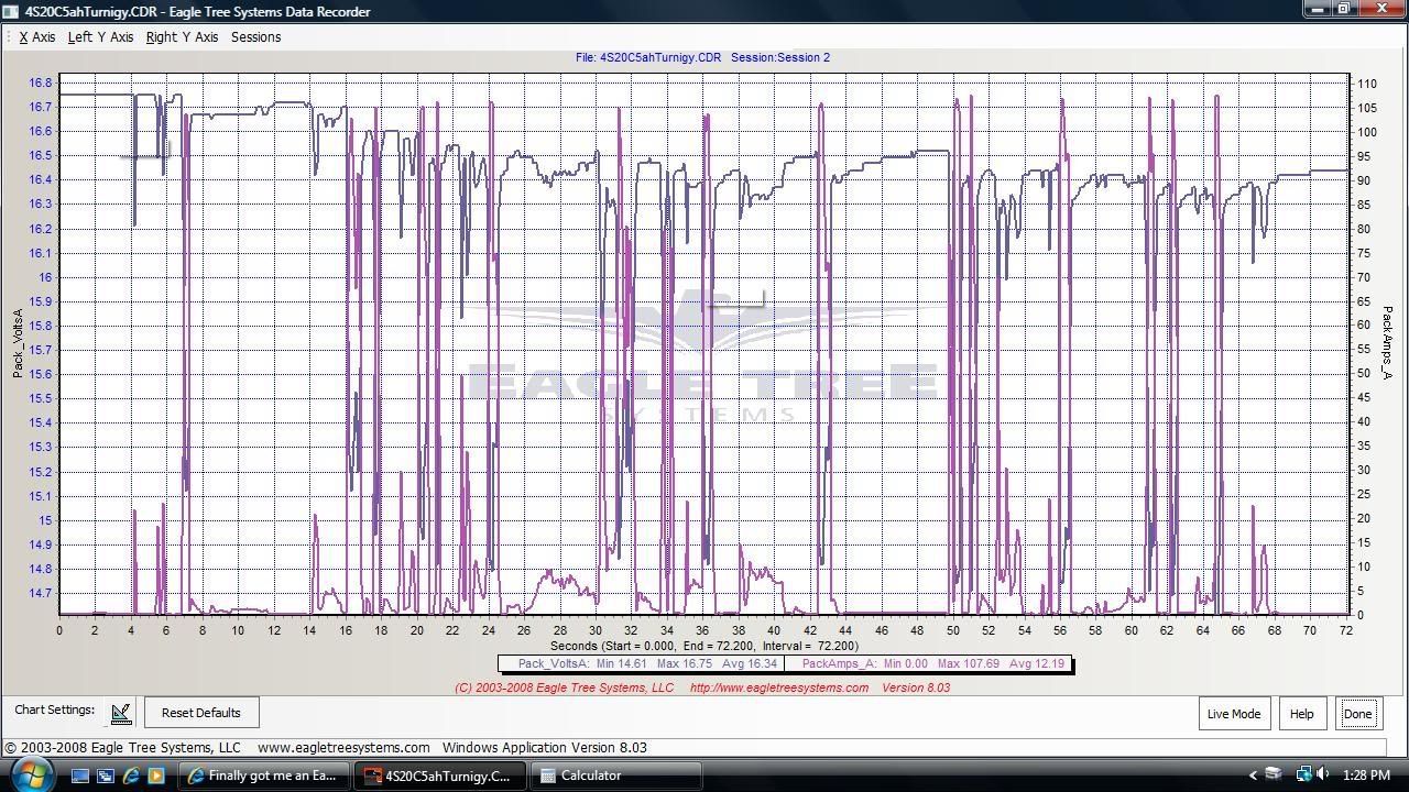
|
|
|
|
|
|
|
|
(#10)
|
|
RC-Monster Brushless
Offline
Posts: 2,085
Join Date: Sep 2007
|
12.27.2009, 04:40 PM
Next up are some packs nearing the end of their useable life.
We've graphed some good packs, now let's do some not so good packs. Flightpower are some GREAT packs IMO, the packs in these graphs are dying of old age AND have many cycles on them. They are 4S 3200mah 30C packs, two of them parallel for 6400mah. 2.97 volts per cell under 108 amp load. Not good, considering the run only lasted 12 minutes to the LVC. These might be ok for a few more cycles in something like a Rustler maybe, but they now need to be retired from MT use IMO. 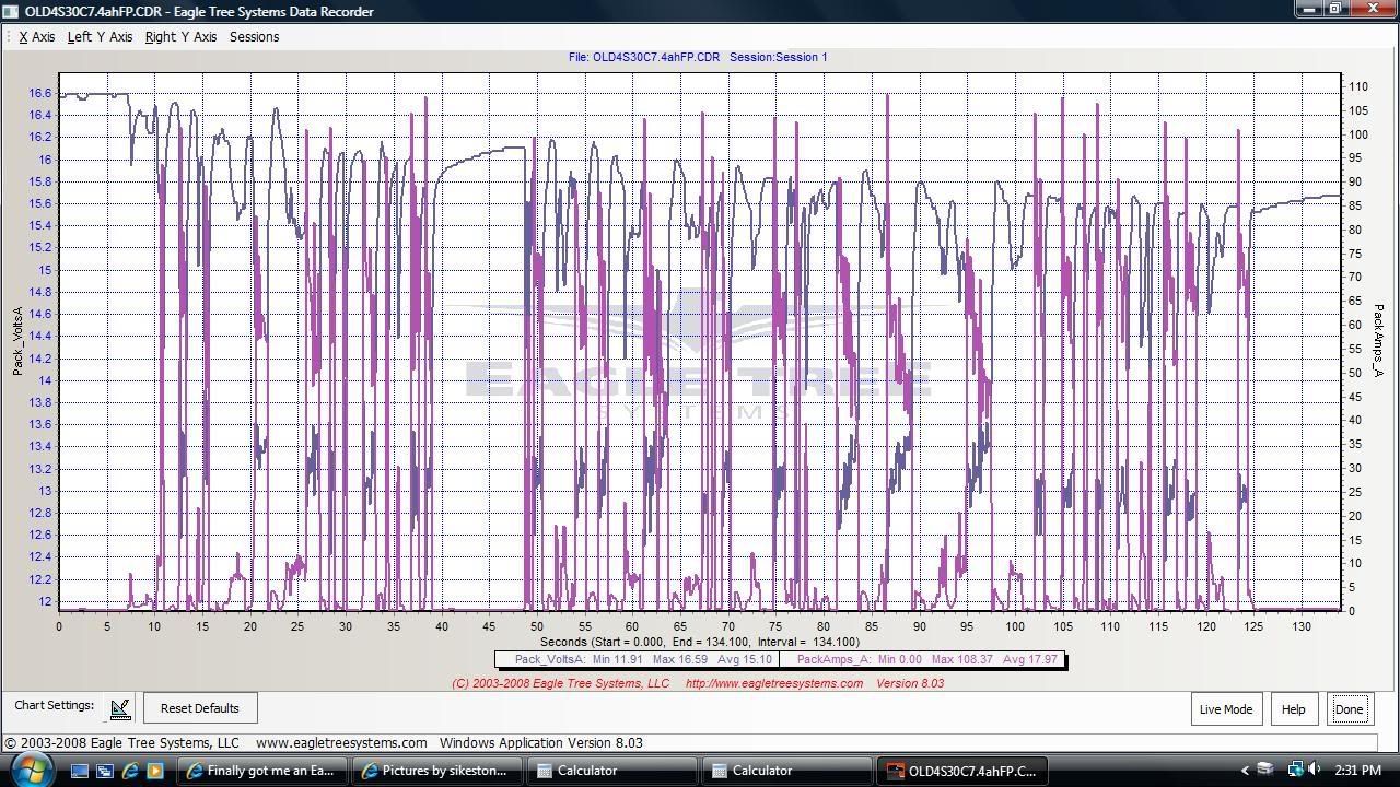
|
|
|
|
|
|
|
|
(#11)
|
|
RC-Monster Brushless
Offline
Posts: 2,085
Join Date: Sep 2007
|
12.27.2009, 04:46 PM
Next up is the end of the run that shows the Truck getting on the LVC.
The LVC is set at 3.2 volts per cell. This graph shows some interesting behavior of the LVC. It appears the LVC does have a reaction time. This is shown where the low pack volts are 10.93 That is 2.73 volts per cell. Hmm........ Once the LVC reacts, it is "regulating" amp draw and hold the LVC to around 12.8 volts. Right where it should be. Interesting. 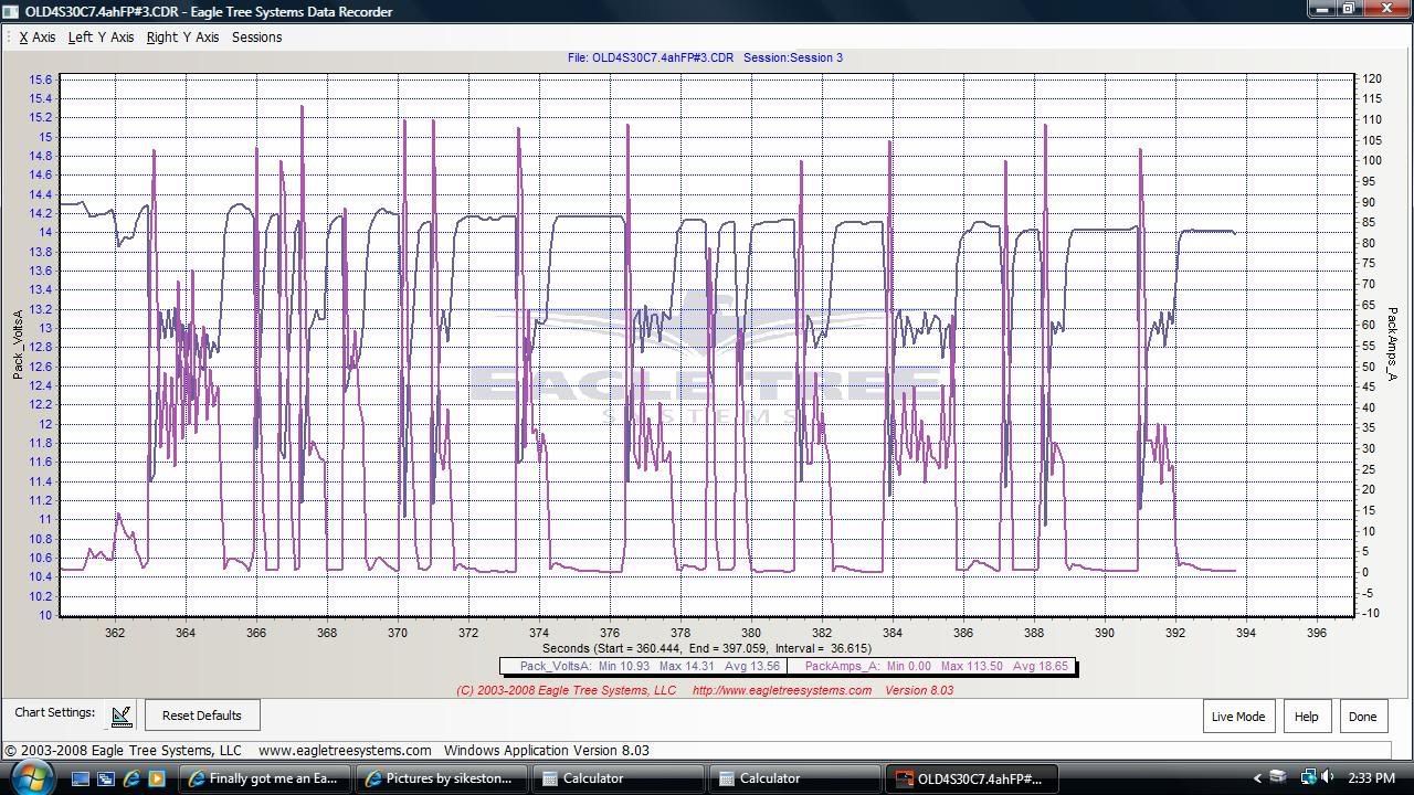
|
|
|
|
|
|
|
|
(#12)
|
|
HV basher
Offline
Posts: 392
Join Date: Jun 2007
Location: Austria (Europe)
|
12.27.2009, 05:10 PM
Are you using the 150A version?
Jazz 55-10-32, Neu 1515/2Y (1100kv), 9s2p A123 (27v), up to 3.1KW Latest video with eagletree Data inserts: Run on asphalt |
|
|
|
|
|
|
|
(#13)
|
|
|
RC-Monster Brushless
Offline
Posts: 2,085
Join Date: Sep 2007
|
12.27.2009, 05:21 PM
Quote:
Amp Draw appears maxed out at 120 Amps with this version. I found that out yesterday when the powerboard melted down on my MMM ESC. Pegged at 120 amps for about 2.5 seconds until I could get the ESC unplugged. Thing really put out alot of smoke too. I didn't think I would ever get that smell out of my nose. LOL I caught it all on the Logger. Unbelieveable! 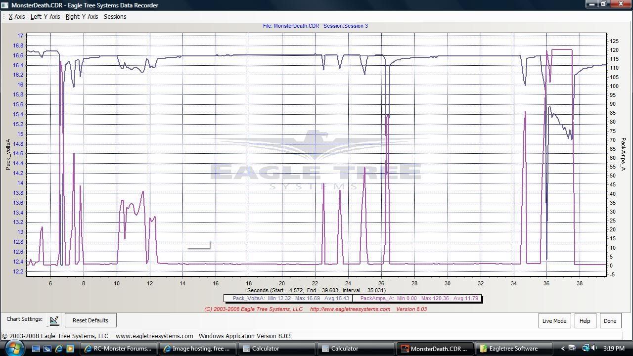
|
|
|
|
|
|
|
|
|
(#14)
|
|
HV basher
Offline
Posts: 392
Join Date: Jun 2007
Location: Austria (Europe)
|
12.27.2009, 06:06 PM
Those 108A peaks made me suspicious and led me to believe you are using a 100A version. My old burned up 100A version recorded similar peaks and also maxed out at 120A. I am now using a 150A version and the graph depicted in the turnigy thread was recorded with the 150A version.
Wow, what happened exactly this early into this run? Did your MMM fail from one moment to the other (as a result of something - braking?) and shorted the batteries. Lipo batteries, Receiver and servo alright? That's an interesting log for sure. Side note about braking: When zooming into a graph you might be able to see voltage rise although amps rise too. This happens when you brake with your ESC and current flows back to the battery. The eagletree logger records positive amps although you are not drawing current from the battery. Jazz 55-10-32, Neu 1515/2Y (1100kv), 9s2p A123 (27v), up to 3.1KW Latest video with eagletree Data inserts: Run on asphalt |
|
|
|
|
|
|
|
(#15)
|
|
|
RC-Monster Brushless
Offline
Posts: 2,085
Join Date: Sep 2007
|
12.27.2009, 06:16 PM
Quote:
I got a deal on this 100 amp version. That's why I got it. My MMM was a V2 version. It probably had 150 packs through it. It will be on it's way back to Castle since Patrick stated all V1's and V2's had a lifetime warranty. Based on that, I'm sure I will receive a Brand New V3 MMM in return. The V2's had their share of problems. The Lipos, Receiver and Servo's are all ok. Yes, I've seen examples of the regenerative braking on zooms of the graphs. It's pretty obvious that it's sending energy back to the batteries while braking. I think this entire thing is really interesting.
|
|
|
|
|
 |
«
Previous Thread
|
Next Thread
»
| Currently Active Users Viewing This Thread: 1 (0 members and 1 guests) | |
 Linear Mode

|
|

Powered by vBulletin® Version 3.8.11
Copyright ©2000 - 2026, vBulletin Solutions Inc.
vBulletin Skin developed by: vBStyles.com
Copyright ©2000 - 2026, vBulletin Solutions Inc.
vBulletin Skin developed by: vBStyles.com